CNC MILLING MACHINE TUTORIAL
Disclaimer: This document is not a supplement to learning the CNC
from Mike or an experienced TA, at no point should you touch the machine
without permission or without completing the outlined steps to program creation
and verification. All programs must be reviewed with Mike or an experienced TA
before loading it onto the machine.
Table of Contents
Blank Preparation & Programming
WCS for Hand Held Lathe Gage Contouring
Operations
The CNC Milling machine becomes an option when moving beyond the simple parts that can be made on the manual machines or the quantity justifies the use of the CNC capability. This tutorial outlines the manufacturing of both the hand held and clamped lathe gages using Fusion 360 as the CAM software. Fusion 360 offers a 3 year license to students, which can be downloaded via the following link: https://www.autodesk.com/products/fusion-360/students-teachers-educators
Watch the VF2 training video as an introduction to the CNC milling machine you will be using: https://www.youtube.com/watch?v=Rh3cMfZzVno
CAD
(SW) and CAM (Fusion360) Tutorial Files
In order to import your file to Fusion 360, click the upload button in the window on the left hand side of the window as seen below.
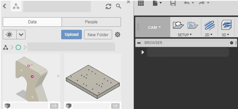
NOTE: Once a file is imported, any modifications to the part will require repeating the upload process and restart the CAM process.
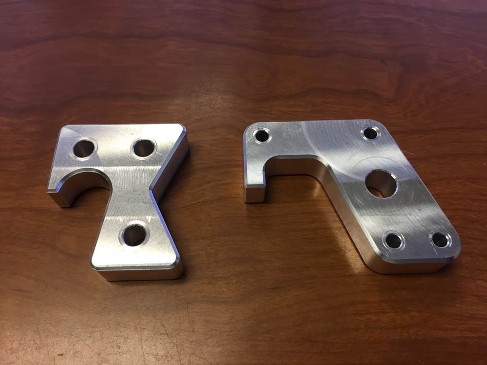
Workholding
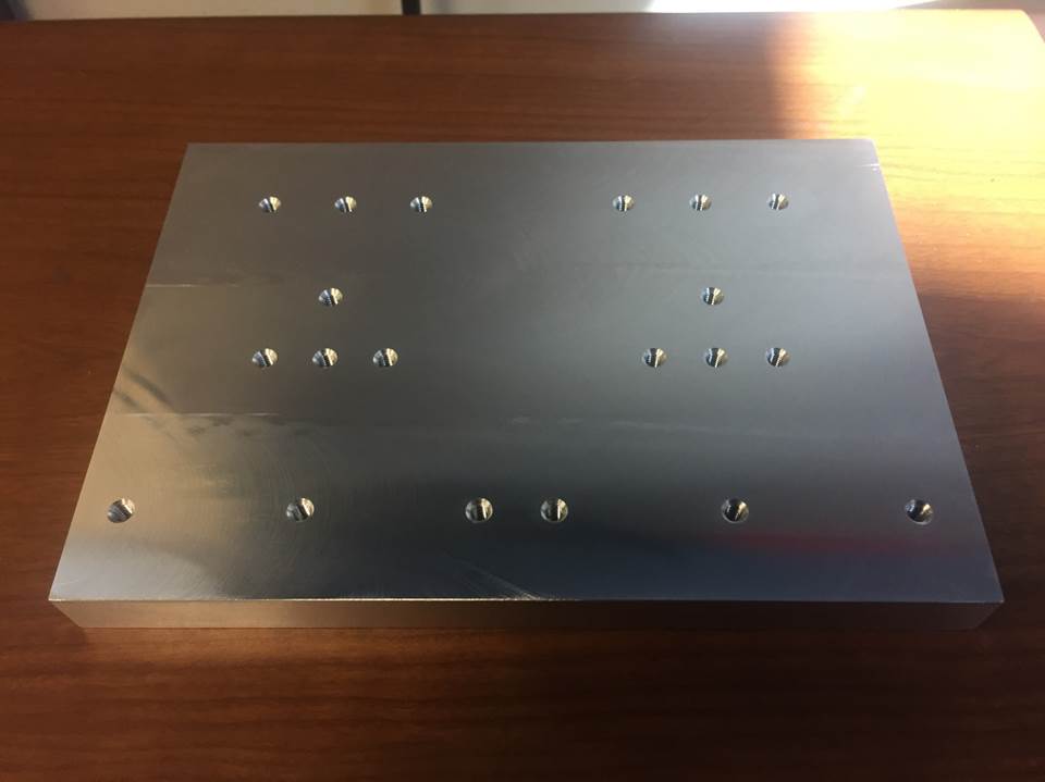
The purpose of the jig plate is to provide a mounting location that provides tool access to the outer geometry of the lathe gages. Without the jig plate or another type of workholding, it is virtually impossible to cut the contour of the lathe gages. The jig plate uses blanks to produce the final lathe gage. The blank is prepared as discussed later in this document and secured to the jig plate with 8-32 fasteners. The jig plate may be cut into during the machining process, but this depth should be minimized to allow for its continued use. As an introduction to the Fusion CAM software, the manufacturing of the jig plate is outlined below.
Fusion – Jig Plate [Return to top]
CAM Setup
Once the Jig plate has been opened in Fusion, a CAM file needs to be created.
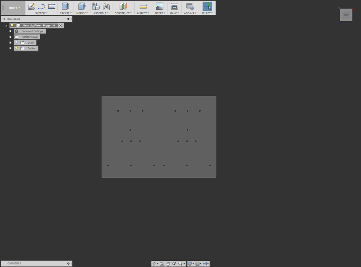
Click on the “Model” icon indicated above and select “CAM.”
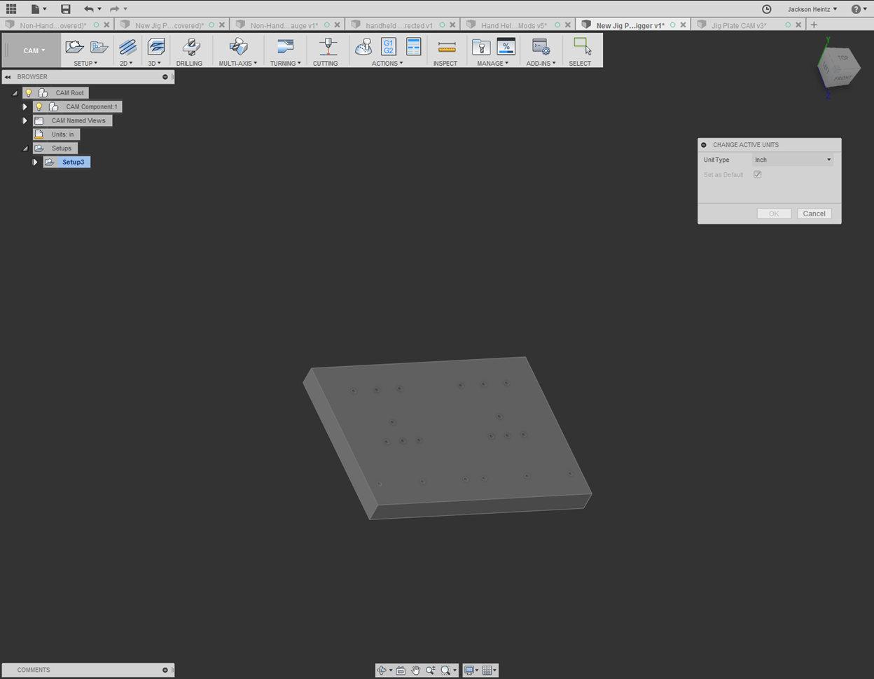
The default units in Fusion are metric. This can be changed to inches through the “Units” tab within the feature tree on the left side of the screen.
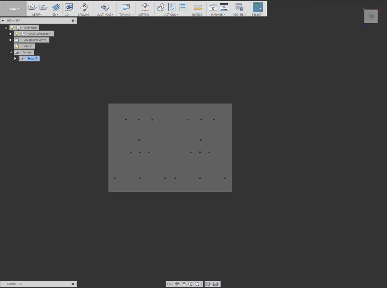
A new setup within the CAM file is needed in order to define the size of the stock from which the jig plate will be cut. After creating a new “Setup” from the indicated icon above, the X, Y, and Z axes can be defined within respect to the jig plate.
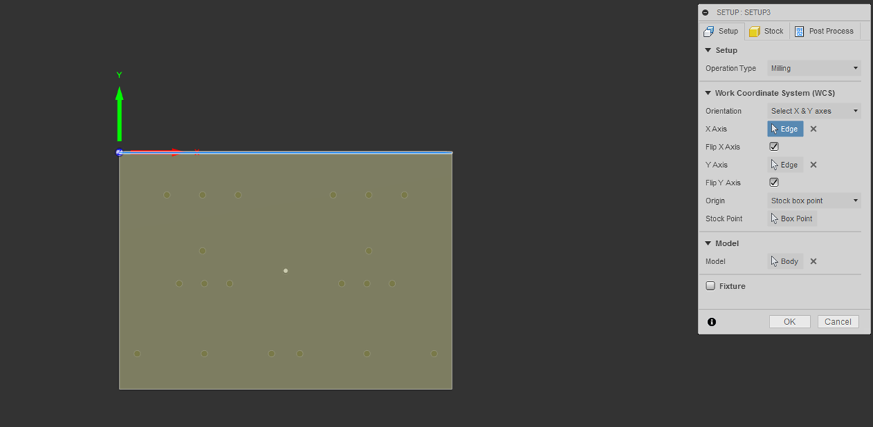
Under the Work Coordinate System (WCS), the orientation option named “Select X & Y axes” was chosen. The first axis you select will define the X axis, and the second will be the Y axis. Directions of each axis can be changed by checking the “Flip Axis” option.
For the purposes of this part, the coordinate system should be identical to the screen shot below. It is critical that each axis is pointing in the correct direction and that the origin is in the proper location. (If incorrect, bad things will happen!J)
The origin is defined by a “Stock Box Point,” and the point shown below was chosen.
This WCS will be identical to the WCS used for both types of lathe gages and will be further discussed in each subsequent section.
NOTE: The origin exists at the TOP SURFACE of the stock box.
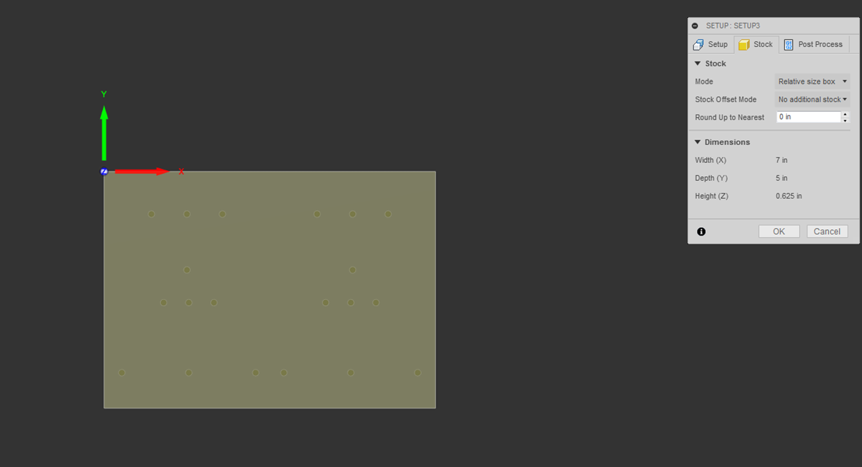
Under the “Stock” tab of the setup, select the options “Relative size box” for mode and “No additional stock” for Stock Offset Mode.
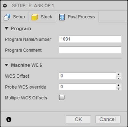
Under the “Post Process” tab of the setup, you can define a program name/number. Under “Machine WCS,” the “WCS Offset” is set to zero, which corresponds to Work Offset G54.
In Fusion, WCS Offset 0 and 1 both correspond to Work Offset G54.
Additionally, WCS Offset 2 through 6 correspond to Work Offset G55 through G59.
NOTE: Do not use Work Offset G57 on the TM2. This offset is used for the wheel hub program and stores the center line of the chuck.
After defining the WCS and stock size, you can now begin programming each operation.
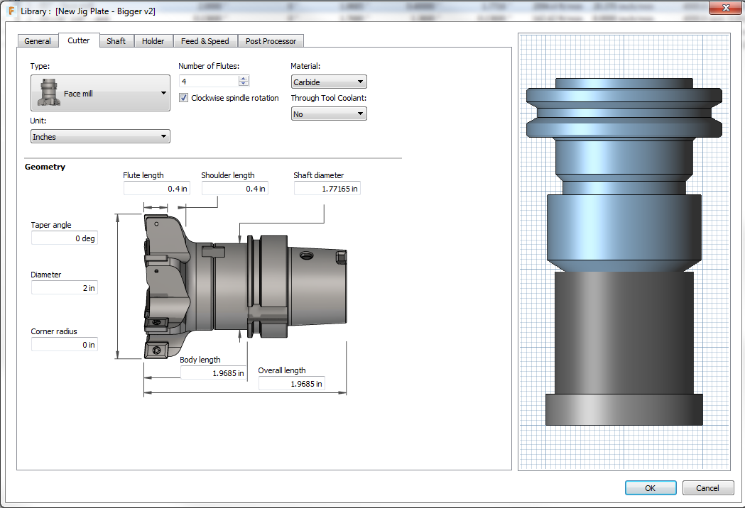
In this section, the proper tool setup for a 2” face mill is illustrated and explained.
After creating a new tool in the tool library, the geometry of the tool must be established.
The following parameters were used for the face mill:
-Number of Flutes: 4
-Material: Carbide
-Diameter: 2 in
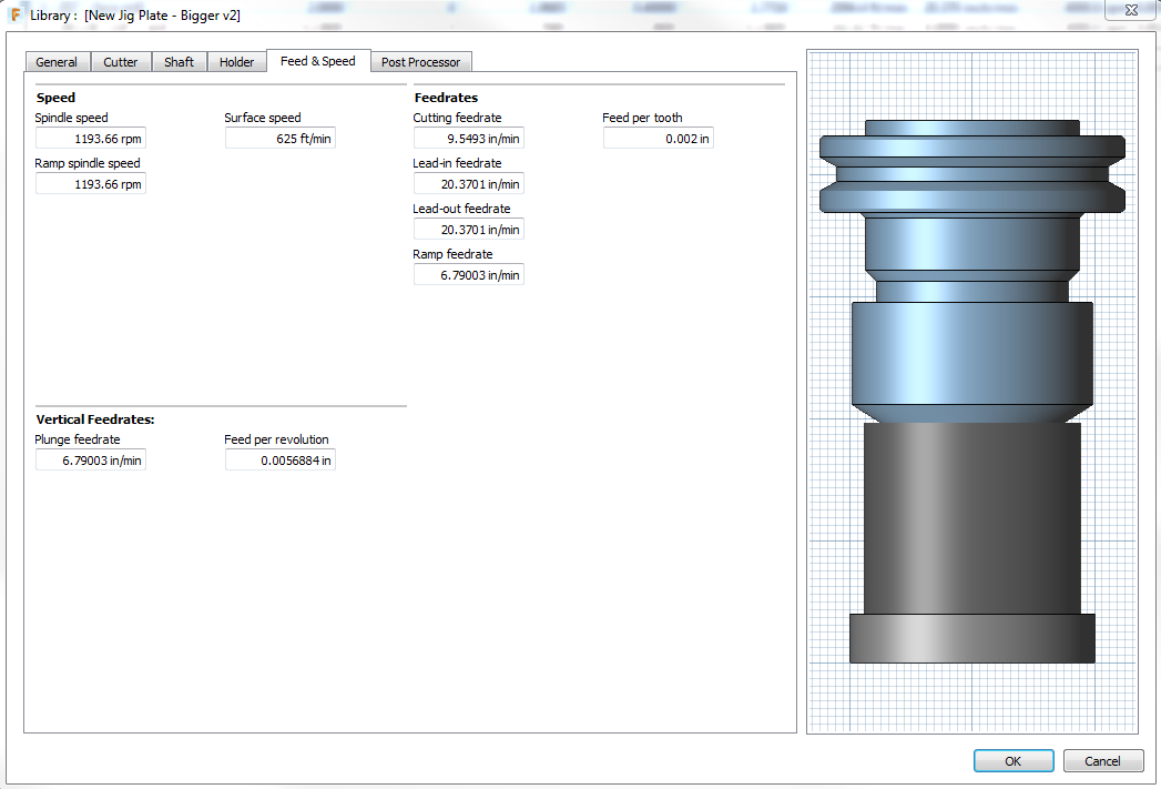
Second, establish the feeds and speeds of the tool through the use of the speeds and feeds document linked below.
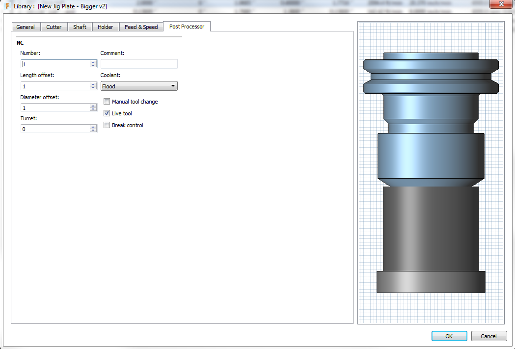
Finally, establish the tool number, length offset, and diameter offset. Set coolant to “Flood.”
NOTE: It is critical that the length offset number and tool number match each other. If the wrong tool offset is used for a tool, the CNC could crash.
Facing Operation [Return to top]
In order make the top and bottom surfaces of the jig plate parallel, a 2” face mill was used to finish each surface.
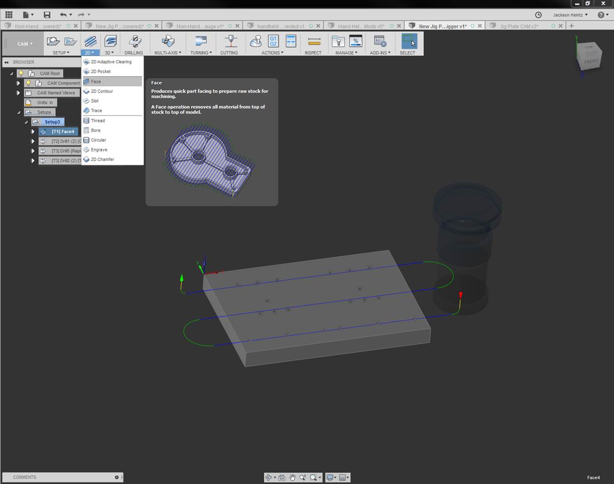
The facing operation is created by selecting “Face” from the “2D” drop-down menu icon shown below.
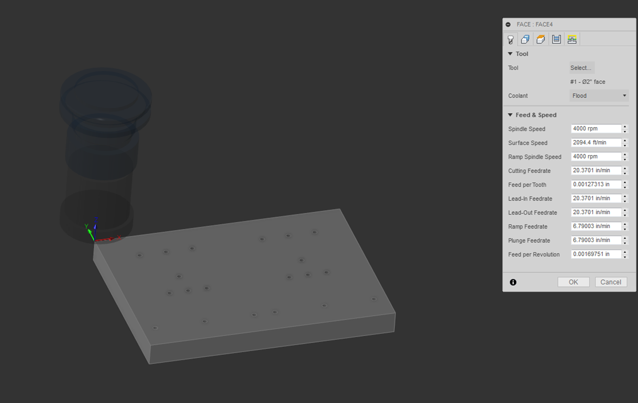
Once created, a tool must be defined. Click on “Select” to open the tool library and select the 2” face mill. For instructions on tool setup, refer to the Tool Setup portion of this document.
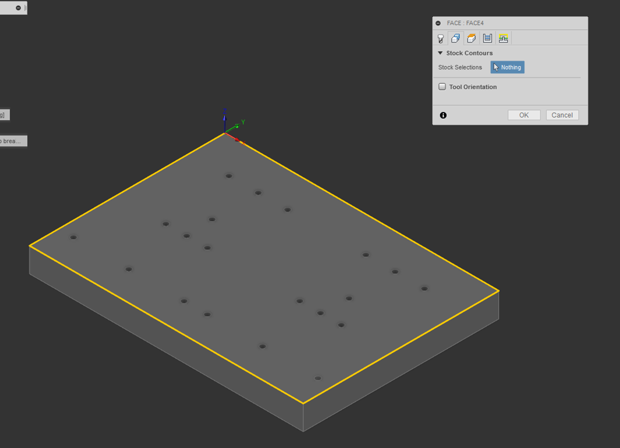
The next part of the facing operation is to select the portion of the plate to be faced. The default with no selection is to face the entire stock surface, this is what we want as the entire jig plate needs to be finished.
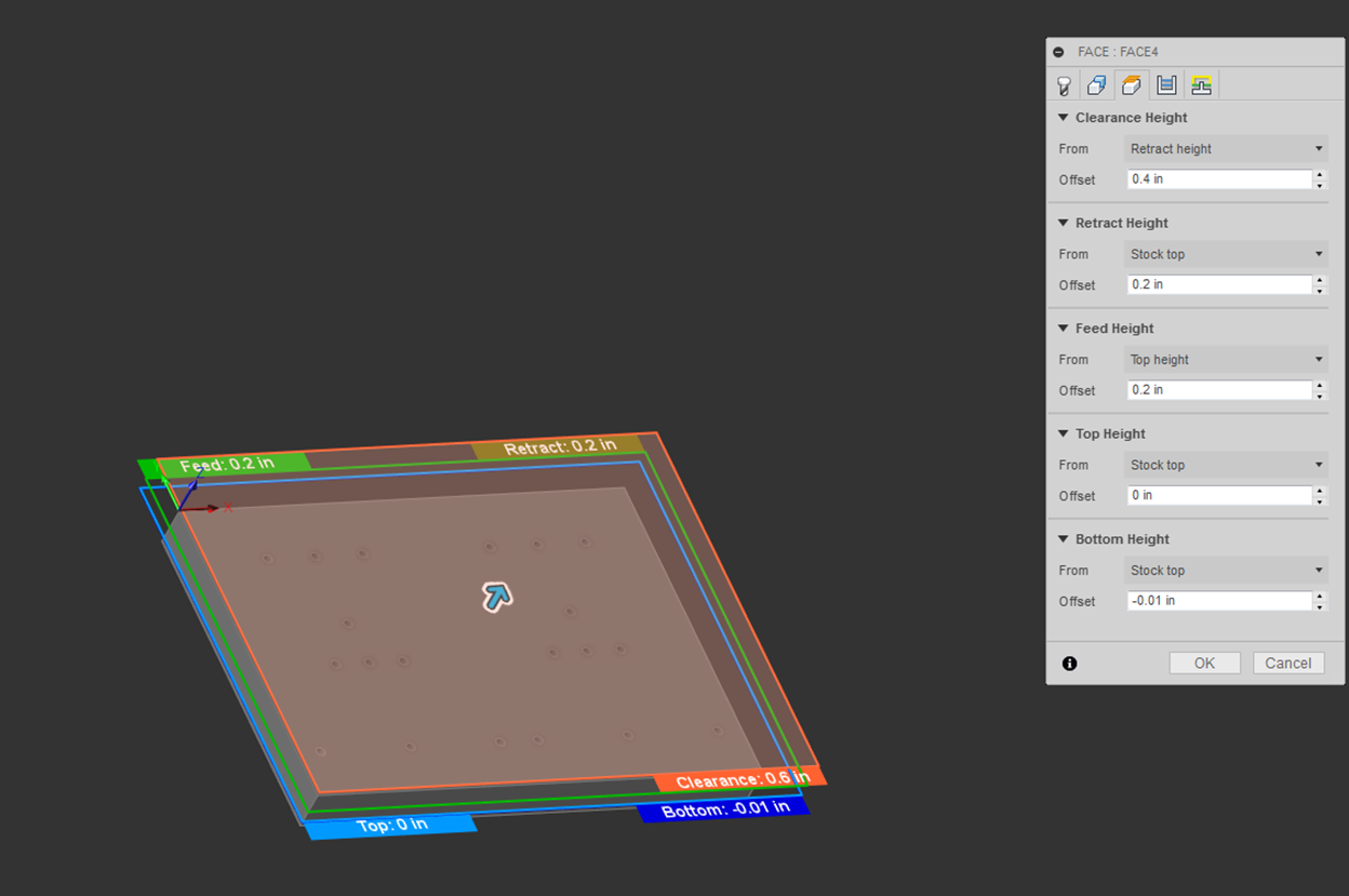
Next, multiple height settings must be established. For details as to what a particular height is, highlight your mouse over the item until a description appears.
For the jig plate, 0.010” was removed from top and bottom surfaces.
Due to the fact that the stock size is the same size as the part, the “Bottom Height” is shifted down by the amount to be removed, which is 0.010” in this case.
The top surface of the stock is used to define surface to be faced, so shifting the surface down 0.010” allows the face mill to travel 0.010” beneath the surface of the stock.
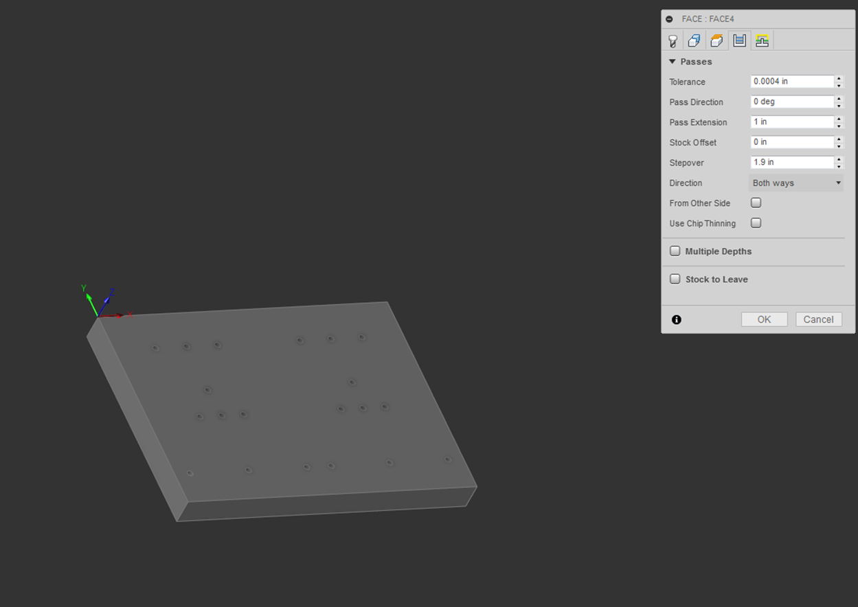
The next tab allows you to change parameters affecting “Passes.”
“Pass Extension” makes the toolpath travel farther than the default. To allow the 2” face mill to travel completely off the part between passes, the path was extended by 1.0”.
The “Stepover” was changed to 1.9”, which allows for 0.100” overlap between passes.
Cutting direction can be changed under “Direction.”
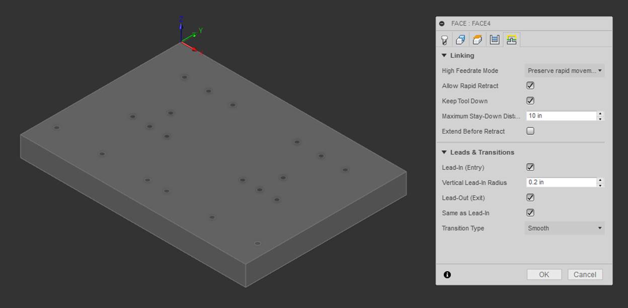
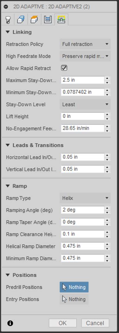
The following parameters were used for linking, leads, and transitions.
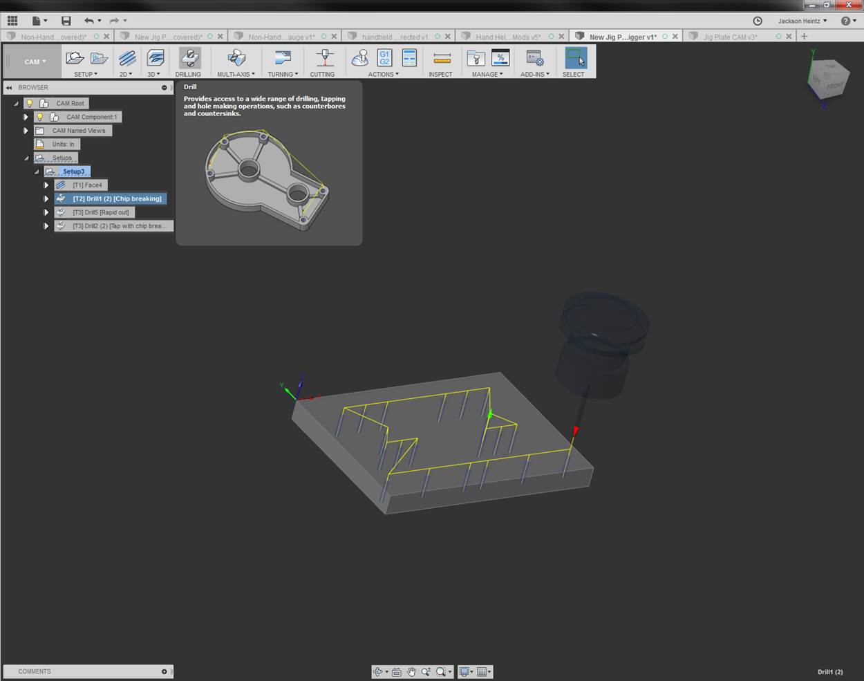
Drilling Operation [Return to top]
In order to tap drill the holes needed for the 8-32 fasteners, a drilling operation must be created. The drill size is chosen based on the standard tap and drill chart.
The drilling operation is created by selecting “Drilling” icon shown below.
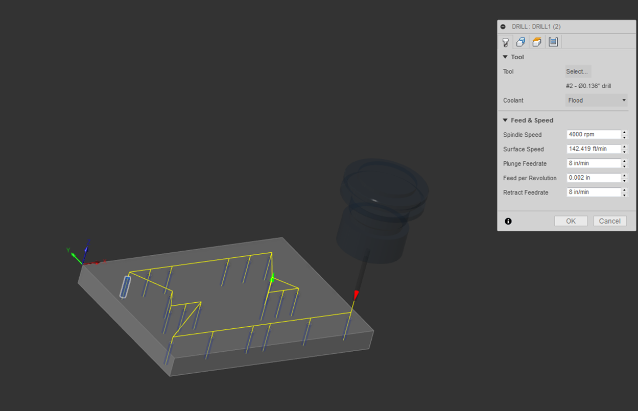
Once created, a tool must be selected. Click on “Select” to open the tool library and create/select the proper sized tap drill. For instructions on tool setup, refer to the Tool Setup portion of this document.
The holes to be drilled must be defined in the “Geometry” tab. For ease of selection, check the “Select Same Diameter” to select all the holes at once.
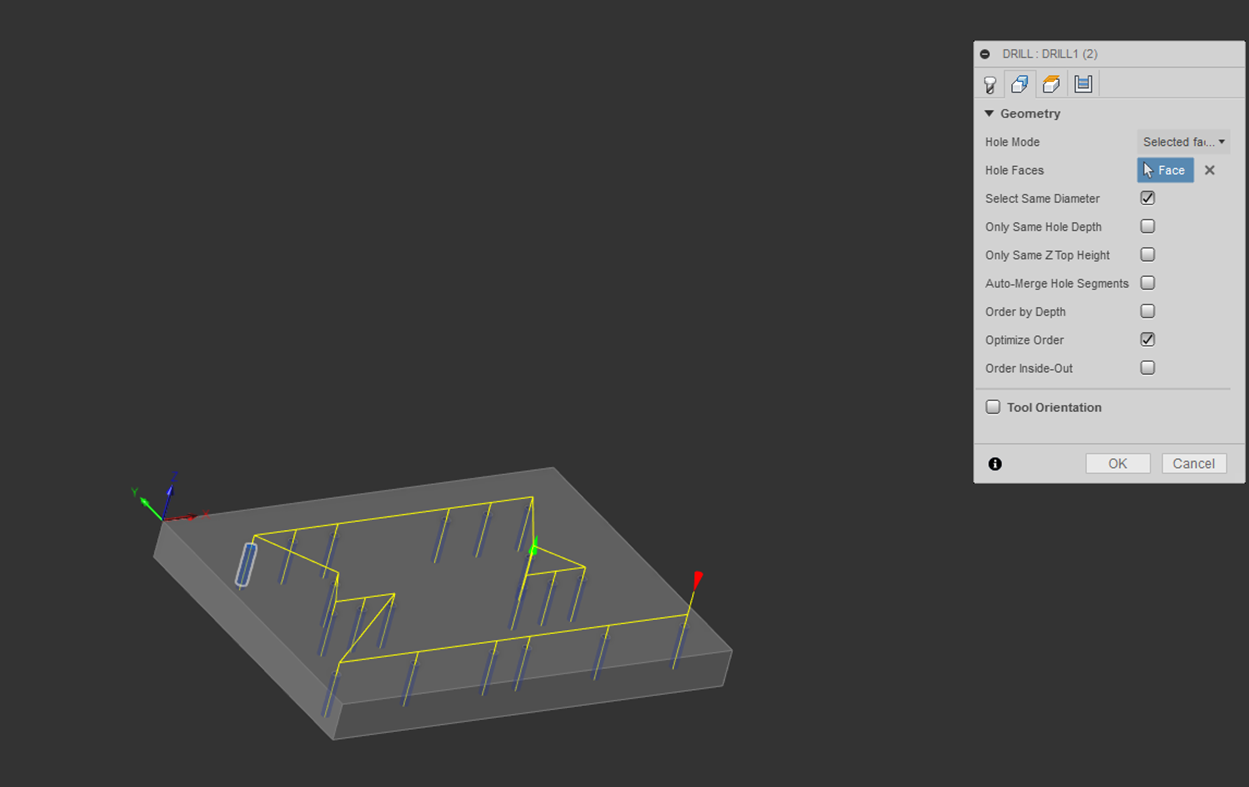
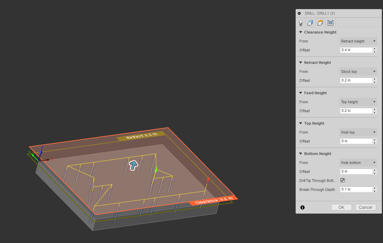
Next, multiple height settings must be established. For details as to what a particular height is, highlight your mouse over the item until a description appears.
The heights shown below were used for tap drilling the jig plate.
It is important to select the “Drill Tip Through Bottom” option and specify a minimum “Break-Through Depth.” If this is not done, only the tip of the drill will reach the bottom surface of the plate.
The minimum break-through depth must be greater than the axial distance from the tip of the drill to the start of the major diameter of the drill.
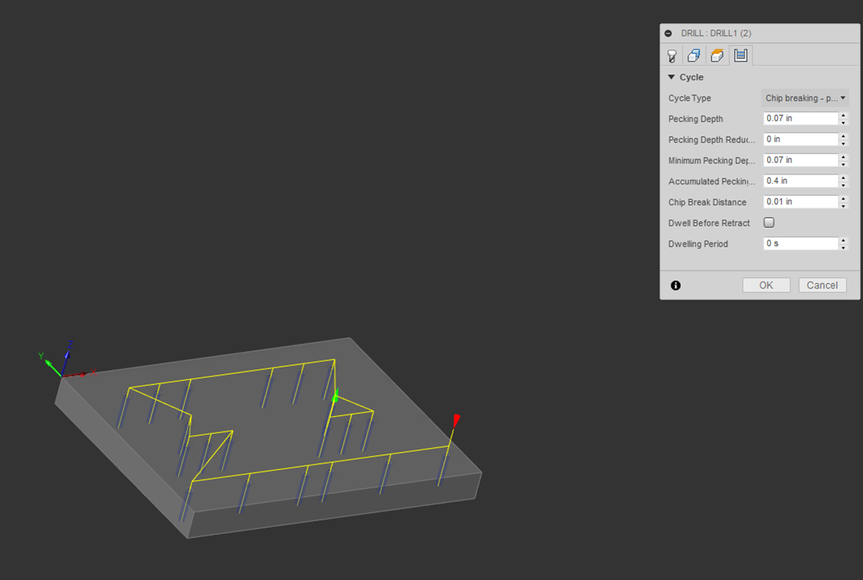
Finally, the drill cycle parameters must be defined. The cycle type used for this drilling operation is “Chip breaking – partial retract.”
For details as to what a parameter is, highlight your mouse over the item until a description appears.
Countersink Setup [Return to top]
When a bolt is threaded into a hole, the first thread closest to the entrance of the hole bears 50% of the load. As the fastener is torqued down, this thread will began to protrude out of the hole thus prohibiting the blank from mating to the top surface of the jig plate.
To avoid this, the top of each hole is countersunk prior to tapping. This allows the first thread to deform into a void below the surface of the jig plate.
In order to countersink the holes needed for the 8-32 fasteners, a drilling operation must be created.
The countersinking operation is created by selecting “Drilling” icon shown below.
Once created, a tool must be selected. Click on “Select”
to open the tool library and create/select the proper sized countersink or
drill/chamfer mill. For instructions on tool setup, refer to the Tool Setup
portion of this document.
The holes to be countersunk must be defined in the
“Geometry” tab. For ease of selection, check the “Select Same Diameter” to
select all the holes at once.
Next, multiple height settings must be established. For details as to what a particular height is, highlight your mouse over the item until a description appears.
The heights shown below were used for countersinking the jig plate, they were calculated based on the geometry of the tool and the fastener. In order to make the countersink effective, countersink 0.010”- 0.020” larger than the major diameter of the fastener. The depth is calculated by using the geometry of the tool and finding where that diameter lies from the tip of the tool.
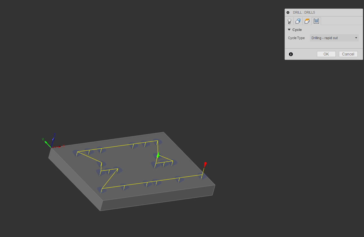
Finally, the drill cycle parameters must be defined. The cycle type used for this chamfering operation is “Drilling – rapid out.”
For details as to what a parameter is, highlight your mouse over the item until a description appears.
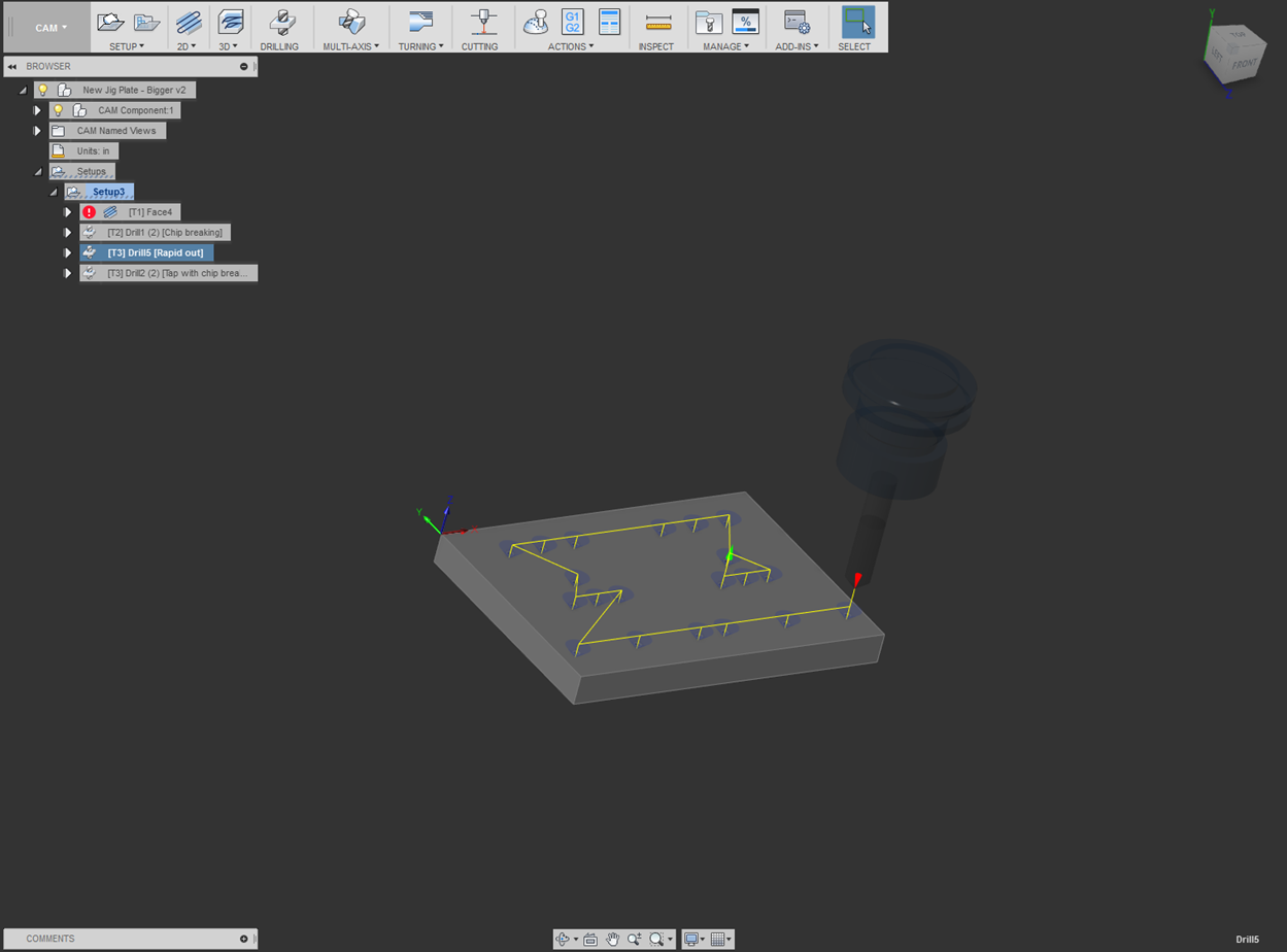
The final operation of the jig plate is to tap the 8-32 holes used to bolt down the lathe gage blanks to the plate. The holes do not necessarily need to be tapped entirely through the part, this is because most of the load is carried by the first 7 threads engaged in the part. The tap being used needs to be measured to ensure the depth of the tap does not exceed its cutting length and a minimum of five threads are cut.
In order to tap the holes needed for the 8-32 fasteners, a drilling operation must be created.
The tapping operation is created by selecting “Drilling” icon shown below.
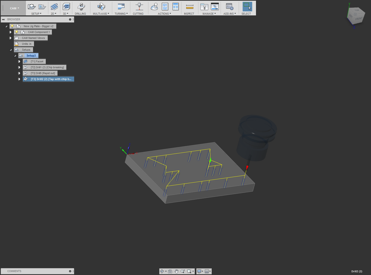
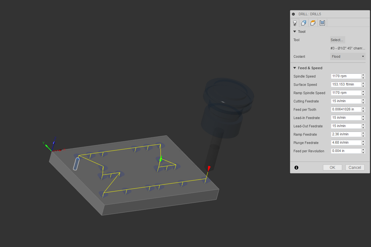
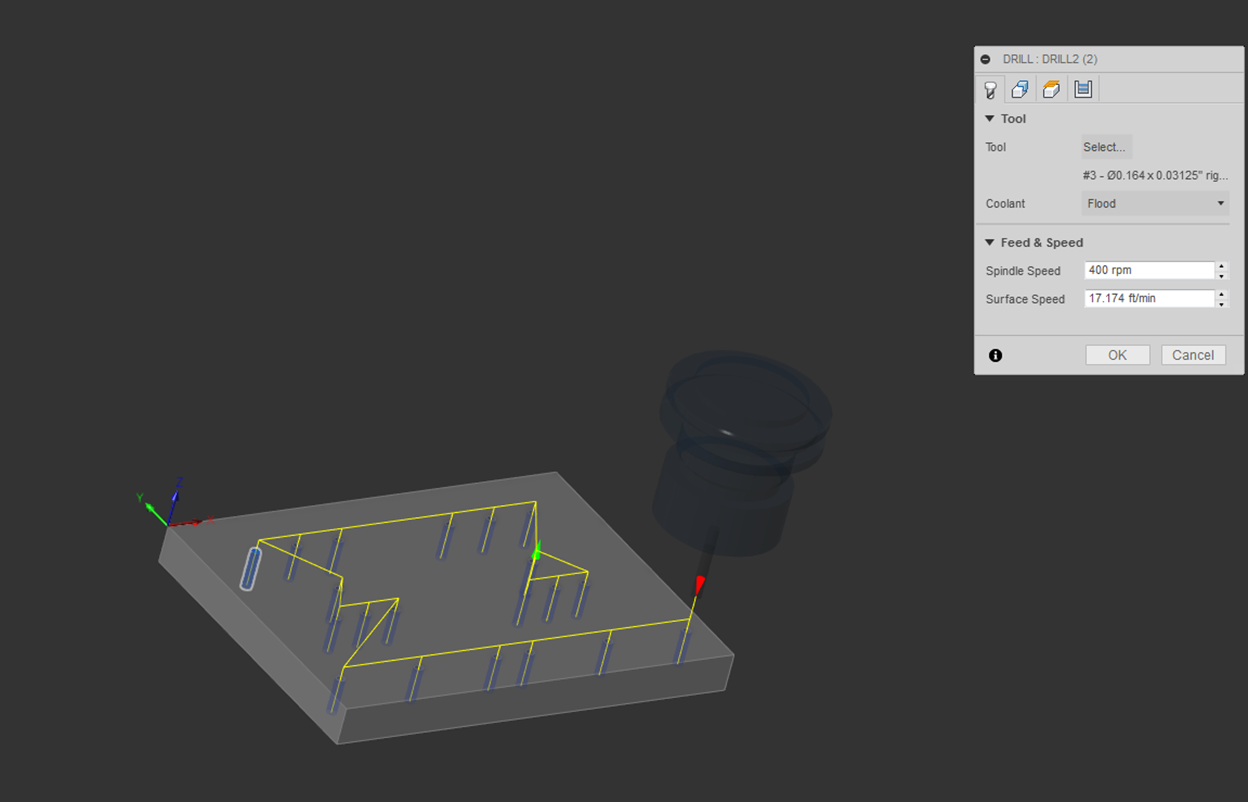
Once created, a tool must be selected. Click on “Select” to open the tool library and create/select the proper sized tap. Proper tool creation/selection is important for this section as the desired threads are cut based on a certain thread pitch set in the tool library itself. For instructions on tool setup, refer to the Tool Setup portion of this document.
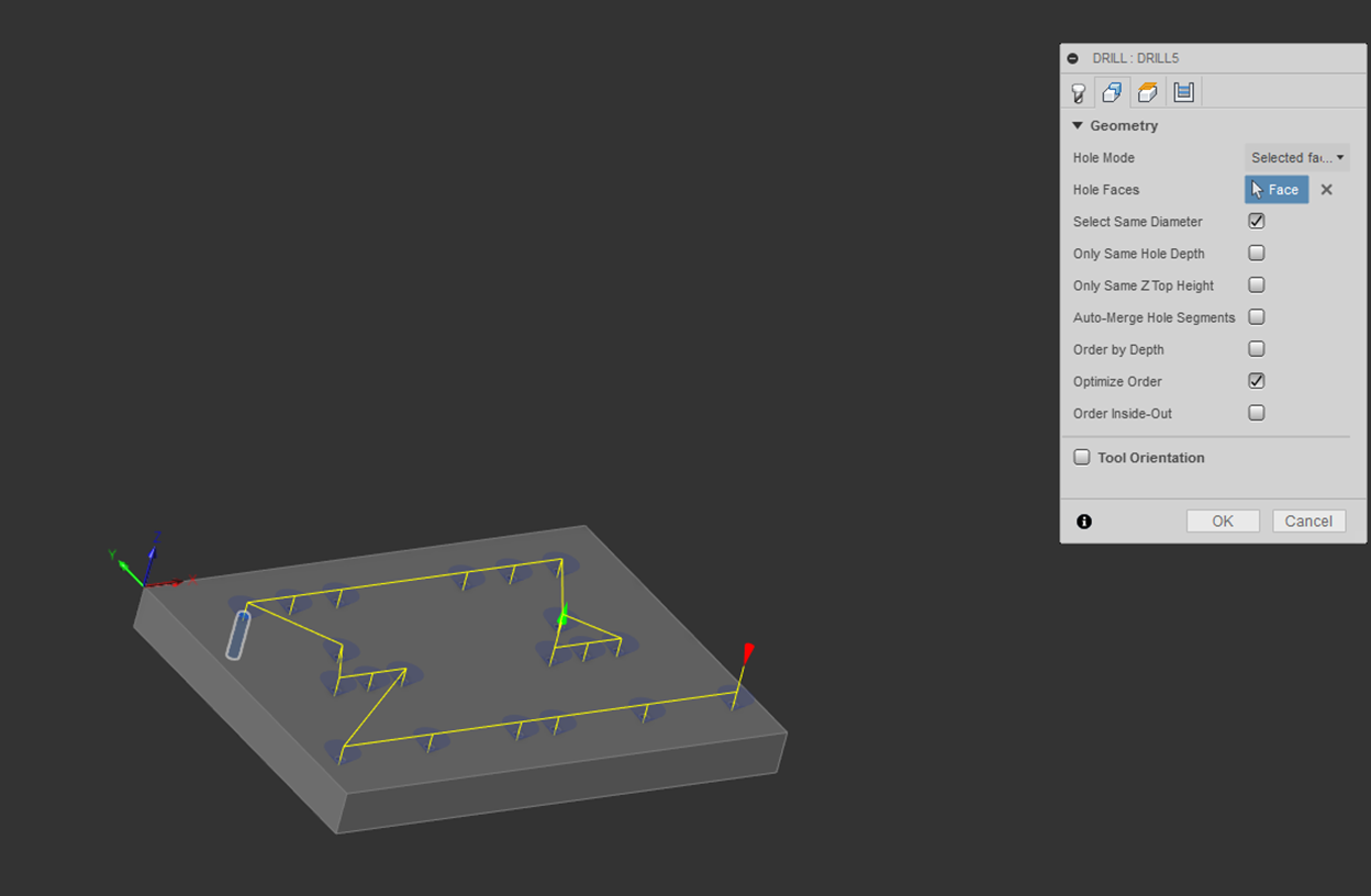
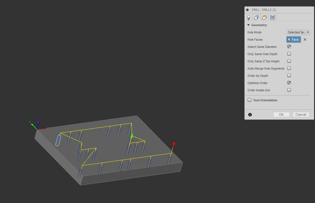
The holes to be drilled must be defined in the “Geometry”
tab. For ease of selection, check the “Select Same Diameter” to select all the
holes at once.
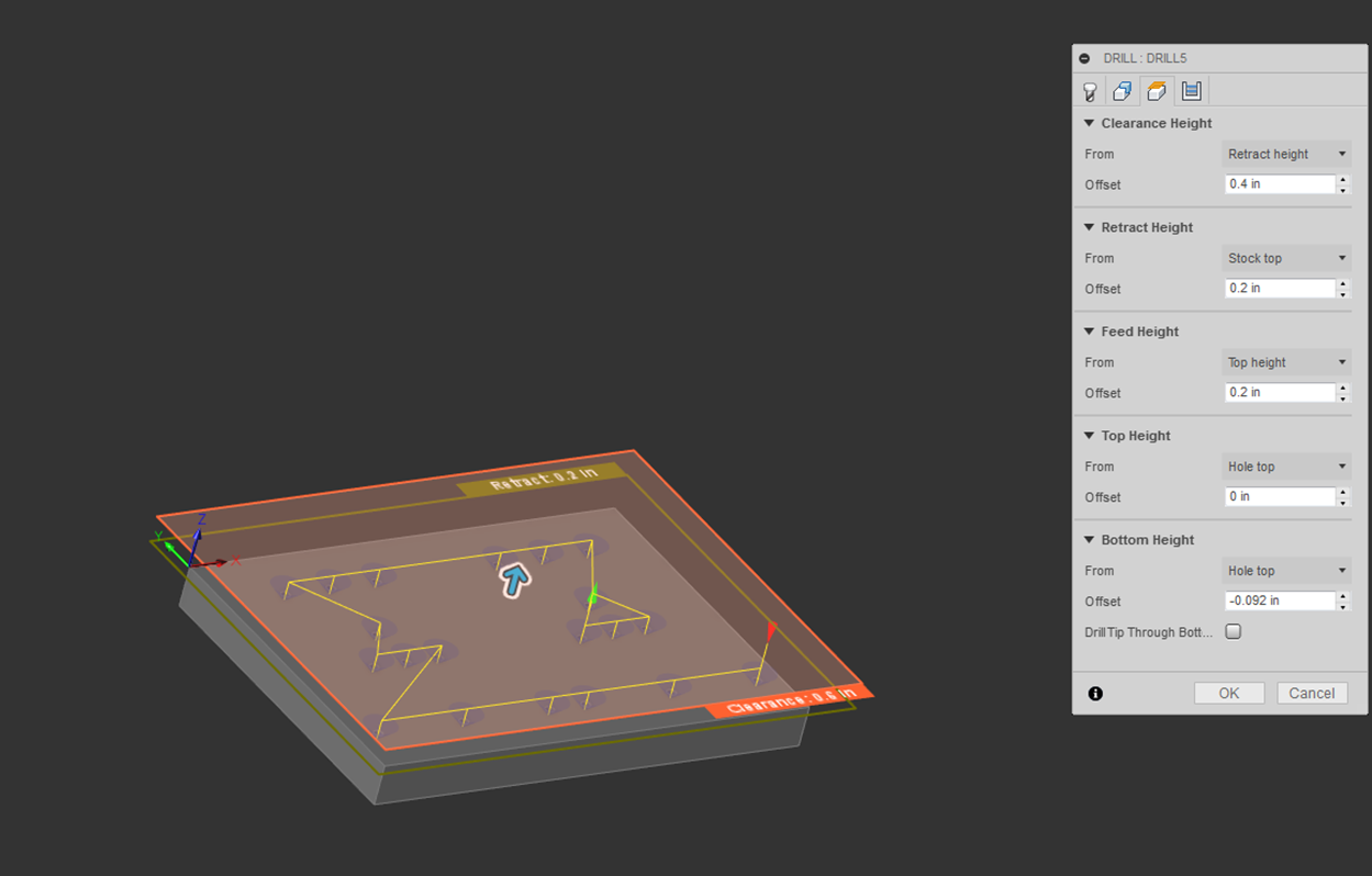
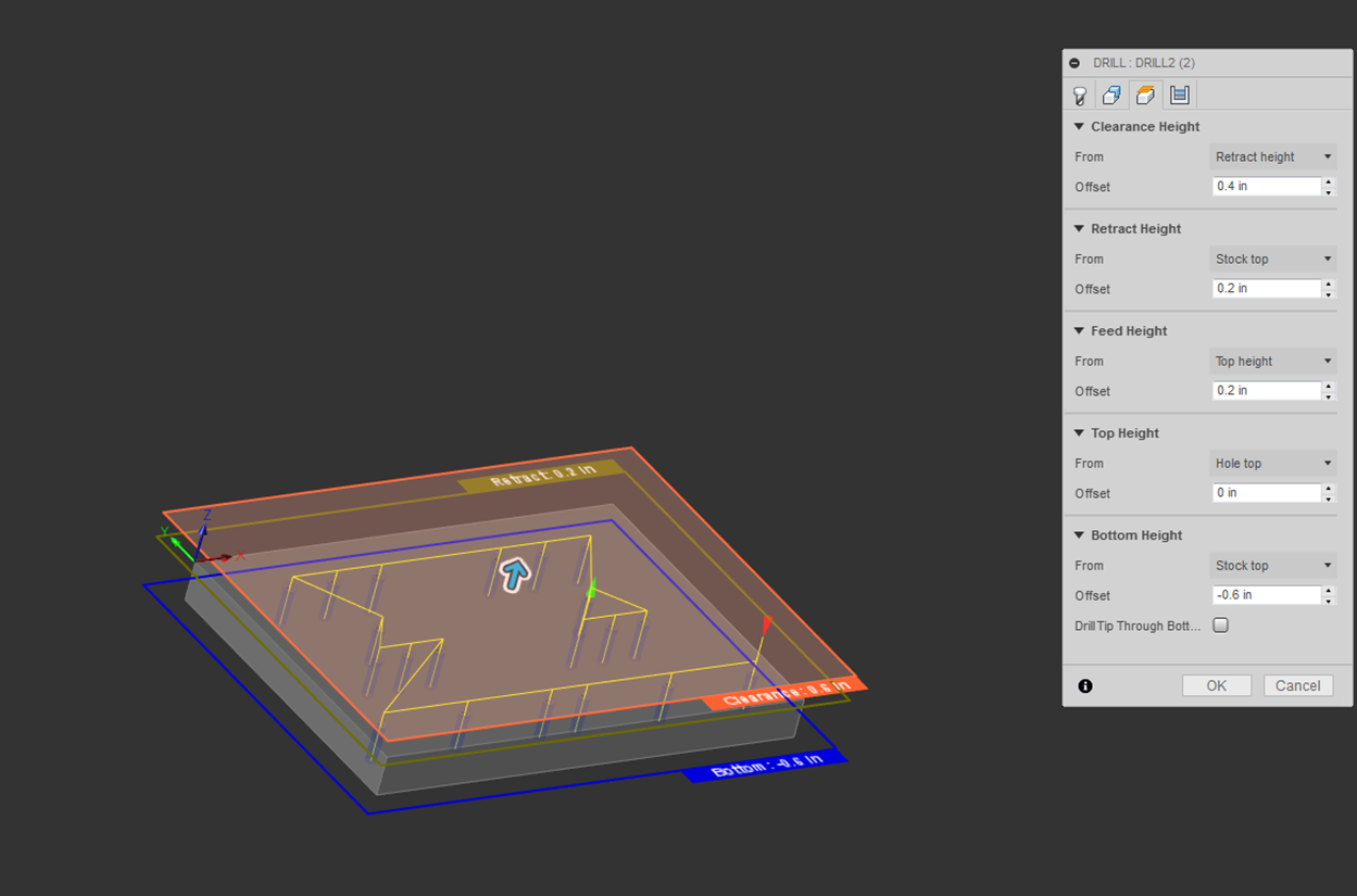
Next, multiple height settings must be established. For details as to what a particular height is, highlight your mouse over the item until a description appears.
The heights shown below were used for tapping with chip breaking (peck tapping) the jig plate.
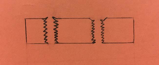
The bottom height is very important, this specifies the depth that the bottom of the tap will go to during the tapping process. Do not confuse the depth with which you send the tool to with the depth of usable threads, however, pay attention to the usable cutting depth of the tap. The usable threads distance changes with the type of tap being used, as seen in the following images. The same cutting depth for a taper, plug, and bottoming tap will produce successively more usable threads in the tapped part by virtue of each less partially formed threads at the tip of the tool.
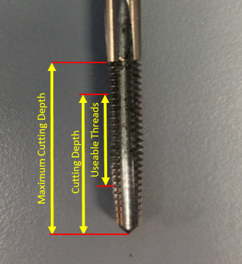
Taper Tap
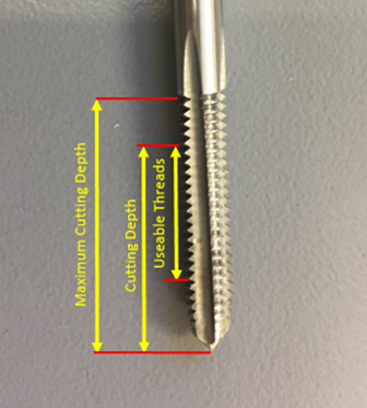
Plug
Tap
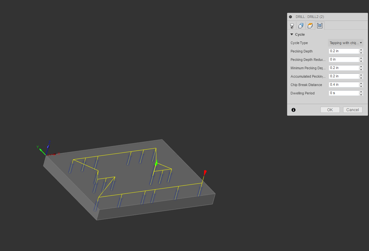
Finally, the drill cycle parameters must be defined. The cycle type used for this tapping operation is “Tapping with chip breaking.”
For details as to what a parameter is, highlight your mouse over the item until a description appears.
The depth for which we set the pecking parameter should be set for 3-5 threads in soft materials like aluminum. This can be calculated by using the same rule of thumb used to calculate five threads of engagement.
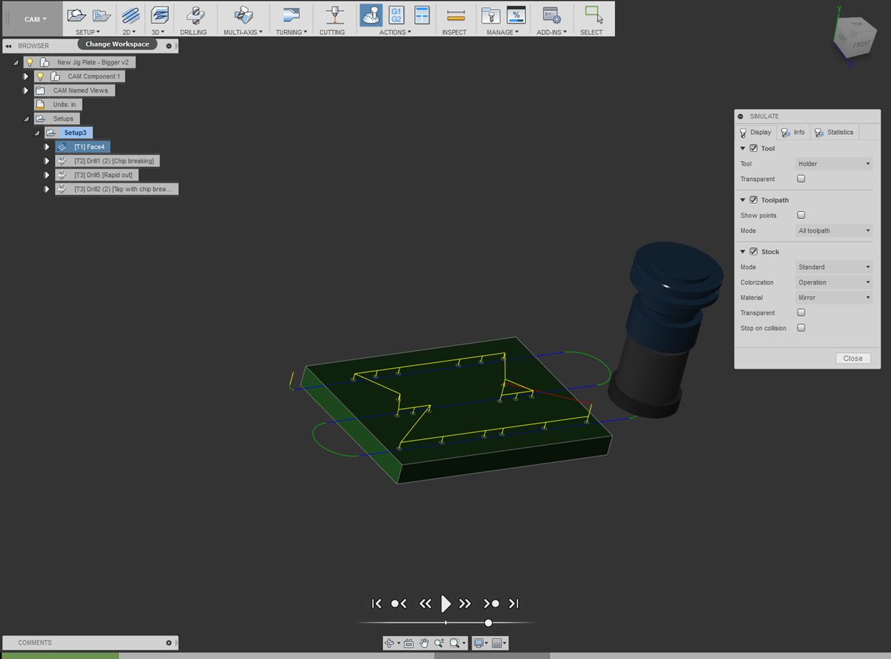
![]()
The Simulation feature allows you to verify that the generated toolpath is as intended.
The controls at the bottom of the screen allow you to control the playback of the animation.
Various options can be enabled/disabled within the tabs of the Simulation window.
Within “Display,” the stock option is enabled which allows you to see the material that is removed.
The “Toolpaths” for each operation are also visible.
Information regarding tool position and operation statistics are provided under the “Info” tab.
Hand Held Lathe Gage – Fusion [Return to top]
Blank Preparation & Programming [Return to top]
Now that we have covered the basics of CAM setup, tool setup, and a few operations (facing, drilling, countersinking, and tapping), you will now practice programming the operations needed for preparing the blank.
The blank requires flat surfaces in order to properly establish the zeroes as defined by the work coordinate system (WCS). Manually machine the bandsaw cut end of the blank that intersects with the origin of the WCS.
The extruded surfaces will be sufficient for the remaining zeroes.
Utilize the information from the above CAM process on the jig plate to complete blank preparation (steps 1-4) on the hand held lathe gage.
View these Fusion 360 introduction videos before proceeding with the CAM:
Drilling and Milling with 2 WCS
https://www.youtube.com/watch?v=g7bu4JuPC_8
2D Adaptive and 2D Contour Single WCS
https://www.youtube.com/watch?v=Do_C_NLH5sw
2D contours, simple 3D contours, and Chamfering
https://www.youtube.com/watch?v=Bd6-BQUCbVA
The programming should follow the layout below:
NOTE: Handheld Lathe Gage Clamped in Vise
1.
Handheld Lathe Gage CAM Part Setup
2.
Tool Setup
3.
Handheld Lathe Gage Operation 1
a. Facing Operation
4.
Handheld Lathe Gage Operation 2
a. Facing Operation
b. Drilling Operation
NOTE: Operations 3 and 4 toolpaths are discussed
following the part manufacturing layout (Bolted to jig plate)
5.
Handheld Lathe Gage Operation 3
a. 2D Adaptive Operation
b. 2D Contour Operation
c. Chamfer Operation
6.
Handheld Lathe Gage Operation 4
a. Chamfer Operation
WCS for Hand Held Lathe Gage
Contouring Operations [Return to top]
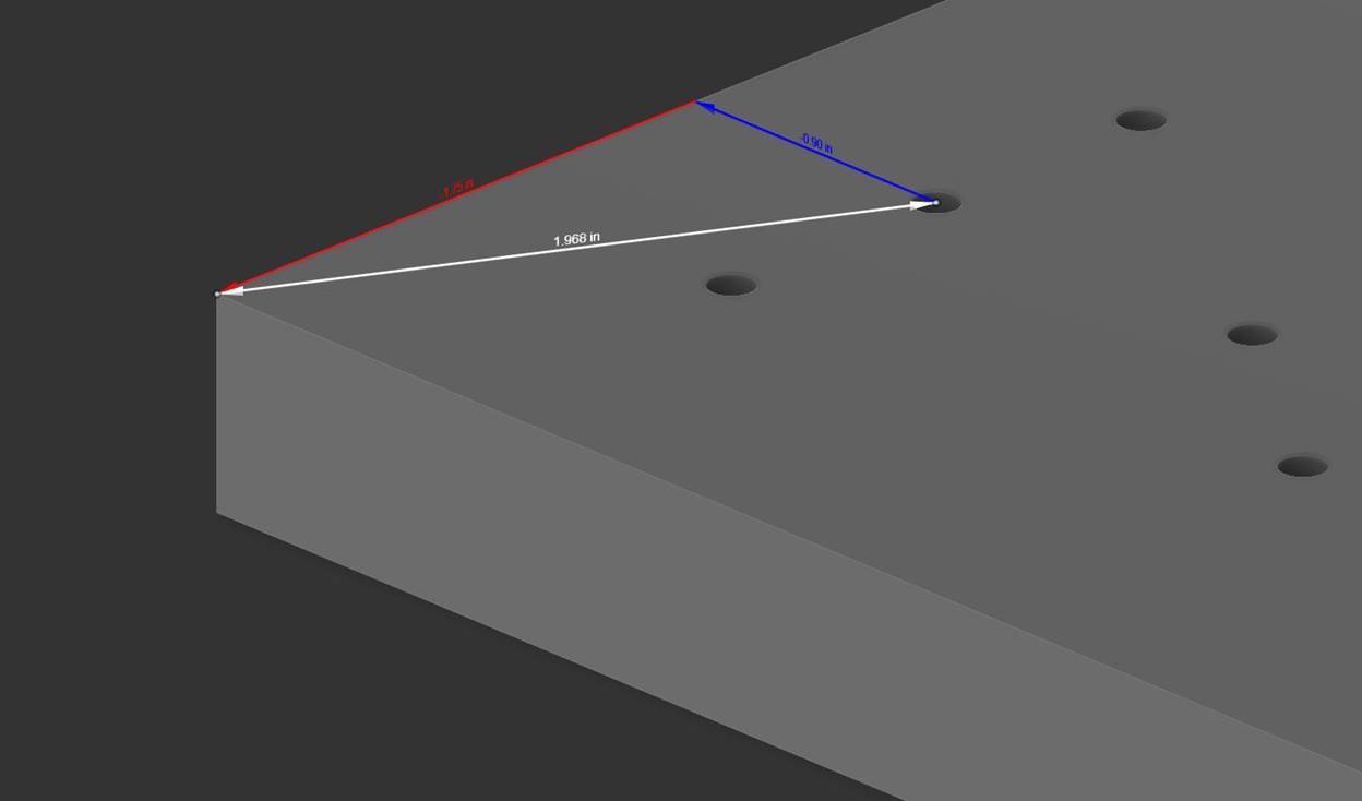
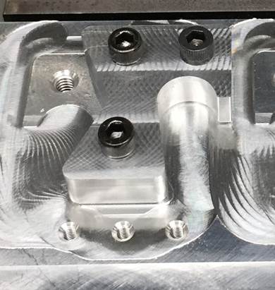
The WCS for the hand held lathe gages is set according to where the lathe gages are on the jig plate. The locations of the lathe gages were determined upon the creation of the jig plate. The location of can be referenced by measuring from one on the holes on the jig plate to the corner that will be used for zeroing. The first operation of the lathe gages is set by measuring from the upper left hand corner of the jig plate to the closest hole (top left fastener pictured below).
The first operation (OP 1) requires the lathe gage to be in orientation shown above.
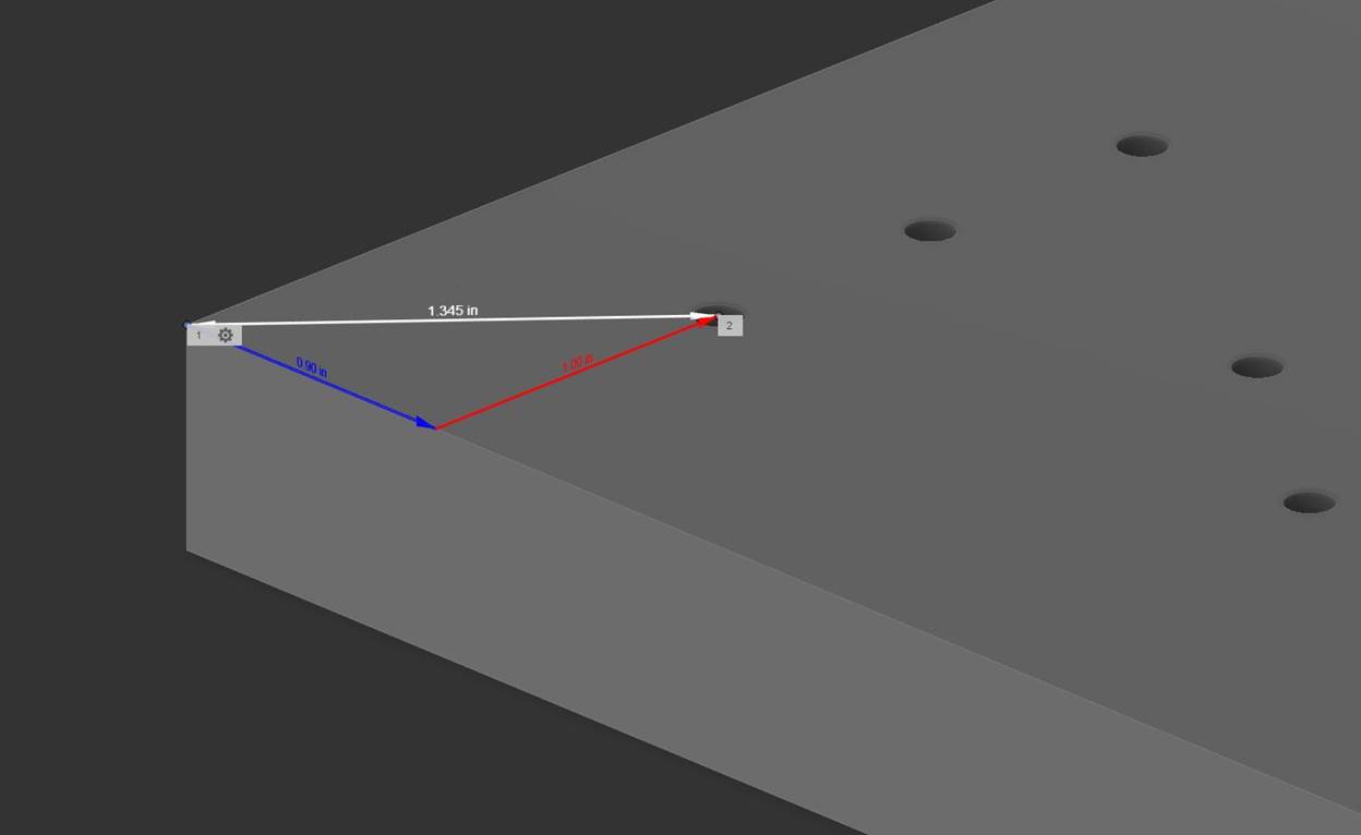
The WCS for OP1 was set by drawing a point on the part at the picture distances on the same plane as face of the jig plate during each operation. We draw this on the same plane that will be mounted to the jig plate because the Z-axis Zero for all WCS is set to the top of the jig plate. The feature measures 1.00” in the X-direction and 0.90” in the Y-direction from the upper corner of the jig plate.
The second operation is set by measuring from the same corner of the jig plate used in the first operation to the hole to the right of the first holes (top left fastener pictured below).
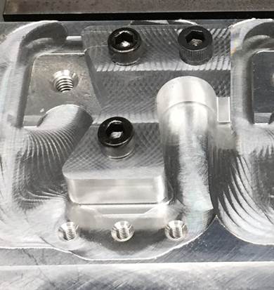
The second operation (OP 2) requires the lathe gage to be in orientation shown above.
The WCS for OP2 was set by drawing a point on the part at the picture distances on the same plane as face of the jig plate during each operation. We draw this on the same plane that will be mounted to the jig plate because the Z-axis Zero for all WCS is set to the top of the jig plate. The feature measures 1.75” in the X-direction and 0.90” in the Y-direction from the upper corner of the jig plate.
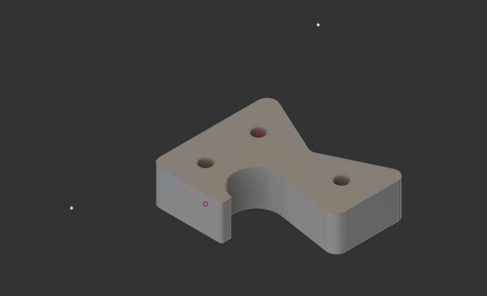
The following image shows the two points that need to be draw in the above locations to establish the two Work Coordinate Systems for Lathe Gage part. The left white dot is the WCS for OP 1 and is drawn in the same plane as the bottom of the part. The right white dot is the WCS for OP 2 and is drawn in the same plane as the top of the part as these plane are mated with the jig plate surface during each operation.
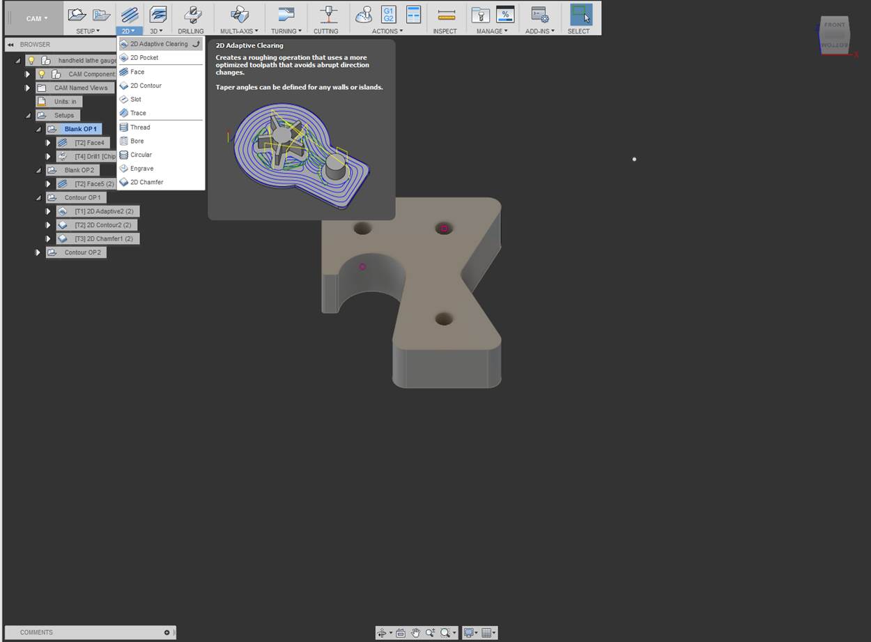
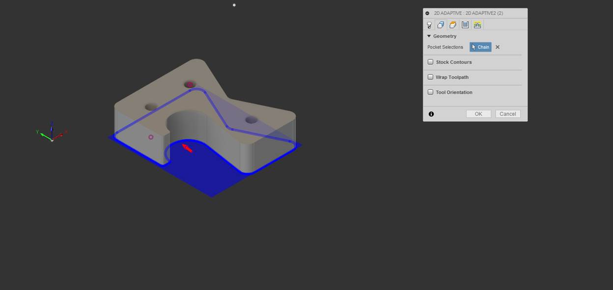
2D Adaptive Clearing is a milling process that removes the "bulk" of the stock from the raw part and roughs it into a shape that's close to the size of the model. This is an extremely powerful tool. It uses an advanced strategy of milling motion that takes a light cut load on the side of the tool, allowing you to take a longer length of cut. This toolpath is commonly referred to as High Speed Machining (HSM). [1]
The 2D adaptive uses a ½”, square end mill to rough out a large amount of the material, this is done to maximize the stiffness of the tool and increase productivity. The ½” end mill cannot produce all the external features of the part and therefore removes all material except a finishing path around the outside contour of the part.
There are two schools of thought when it comes to machining on the milling machine, conventional and high speed machining practices. We implement the ideas associated with high speed machining through a high Depth of Cut (DOC) axially and a low DOC radially. Conventional machining uses low axial depth of cut and high radial depth of cut (as much as the whole diameter of the tool).
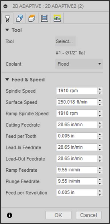
Click on “Select” to open the tool library and select a ½”, 3 flute, carbide end mill. For instructions on tool setup, refer to the Tool Setup portion of this document.
Select the geometry to be
machined.
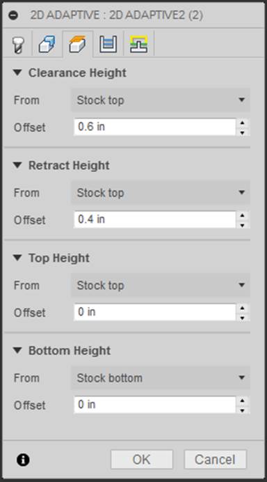
Establish the clearance,
retract, top, and bottom height of the part.
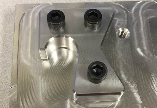
NOTE: It is imperative that you allow for enough clearance between the end mill
and the heads of the fasteners. Clearance of the fasteners is done by measuring
the height of the fasteners and setting clearance and retract heights 0.100”
above the measured height of the fasteners. Setting the a clearance value
larger than 0.100” above all fasteners increases cycle time, however, it is
never a bad thing to have too much clearance. The retact height and clearance
height must clear the top surface of each fastener or this will happen. J
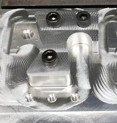
All clearance and
retract heights must clear the heads of the fasteners in the above image.
For passes, an optimal
radial chip load that is 10% of the diameter of the end was chosen.
Stock is left on the part
in the radial direction to allow for a finishing pass. This will be discussed
later.
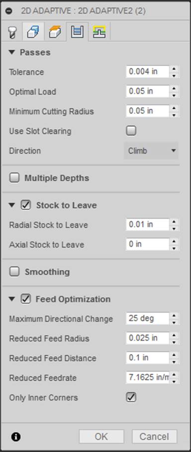
Default parameters for
linking, lead & transitions, and ramp were used.
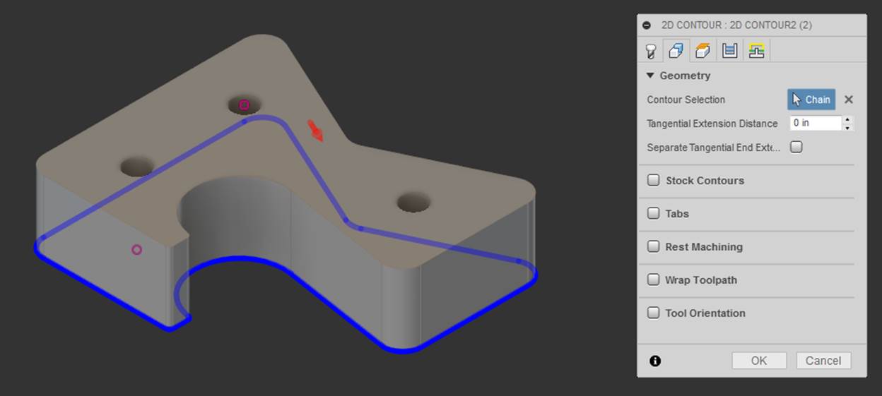
The 2D contour follows up the 2D Adaptive as the operation to finish the outside of the part and uses a tool with the largest radius that produces all the external features.
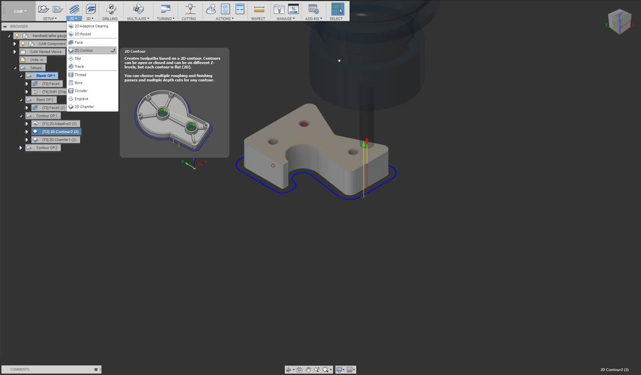
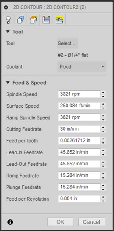
Click on “Select” to open the tool library and select a ¼”, 3 flute, carbide end mill. For instructions on tool setup, refer to the Tool Setup portion of this document.
Select the geometry to be
machined.
Establish the clearance,
retract, top, and bottom height of the part.
NOTE: It is imperative that you allow for enough clearance between the end mill
and the heads of the fasteners. Clearance of the fasteners is done by measuring
the height of the fasteners and setting clearance and retract heights 0.100”
above the measured height of the fasteners. Setting the a clearance value
larger than 0.100” above all fasteners increases cycle time, however, it is
never a bad thing to have too much clearance. The retact height and clearance
height must clear the top surface of each fastener or this will happen. J
All clearance and
retract heights must clear the heads of the fasteners in the above image.
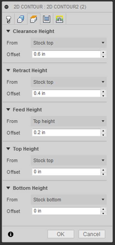
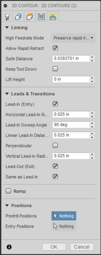
The following parameters were used for passes; roughing passes, smoothing, and feed optimization and will be discussed in lab. For details as to what a particular item is, hover your mouse over the item.
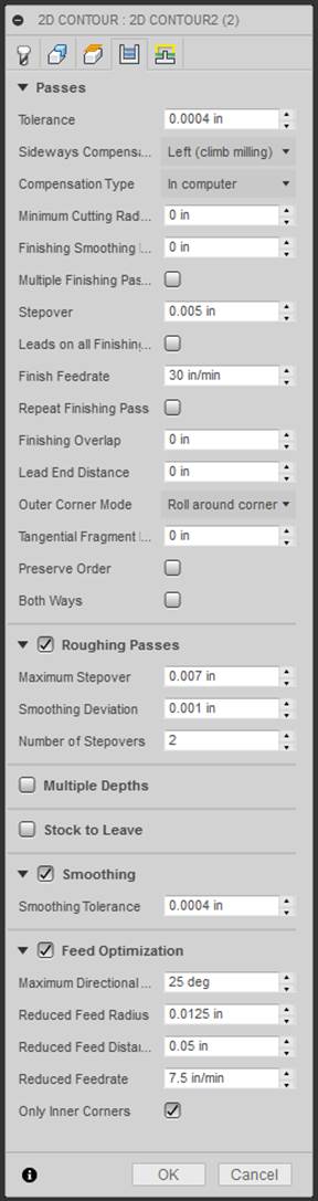
The following parameters were used and will be discussed in lab. For details as to what a particular item is, hover your mouse over the item.
The chamfering operation follows the 2D contour as the final operation on this side of the lathe gage.
NOTE: This operation uses a 45 degree chamfer mill, as this is a milling operation and not a hole creation operation.
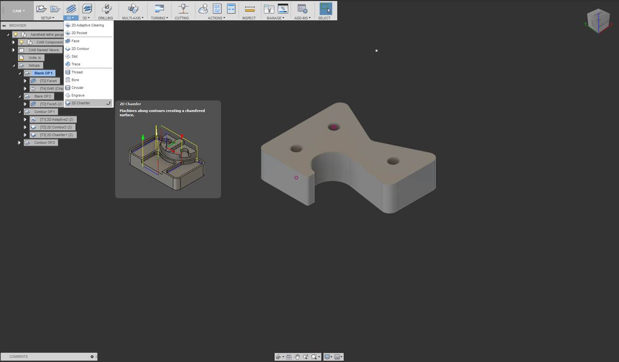
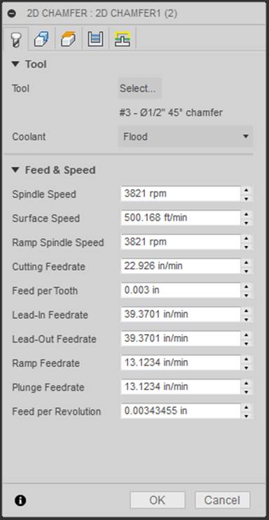
Click on “Select” to open the tool library and select a ¼”, 2 flute, 45 degree carbide chamfer mill. For instructions on tool setup, refer to the Tool Setup portion of this document.
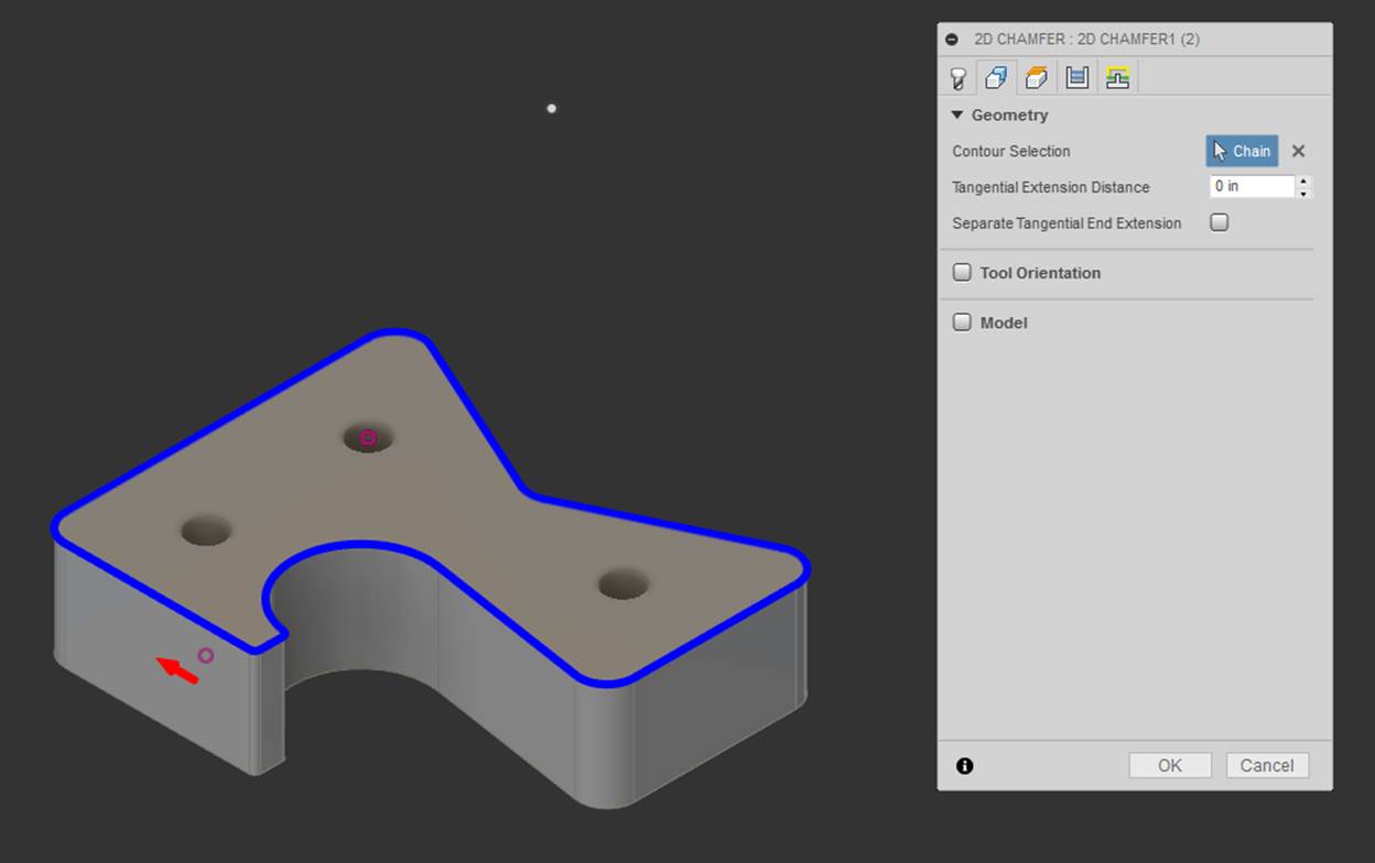
Select the geometry to be
machined.
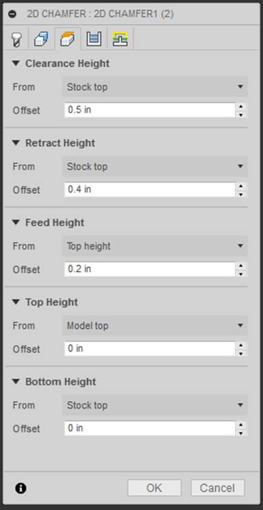
Establish the clearance,
retract, top, and bottom height of the part.
NOTE: It is imperative that you allow for enough clearance between the end mill
and the heads of the fasteners. Clearance of the fasteners is done by measuring
the height of the fasteners and setting clearance and retract heights 0.100”
above the measured height of the fasteners. Setting the a clearance value
larger than 0.100” above all fasteners increases cycle time, however, it is
never a bad thing to have too much clearance. The retact height and clearance
height must clear the top surface of each fastener or this will happen. J
All clearance and
retract heights must clear the heads of the fasteners in the above image.
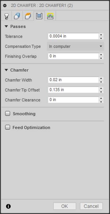
The following parameters were used and will be discussed in lab. For details as to what a particular item is, hover your mouse over the item. It is incredibly important in the case of this part that we set the chamfer tip offset to a value that allows a larger portion of the tool to be used. This value is important as it sets how far in the side of the tool will come, the tool has to clear the fasteners as it make the pass around the side of the part. The closer to the largest diameter of the chamfer mill we get the more radial clearance we will gain from the fasteners.
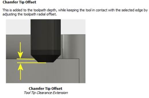
NOTE: As you move up the tool, the radial overlap of the tool on the part decreases. In other words, the tool does not move as far onto the part with a larger value set for chamfer tip offset.
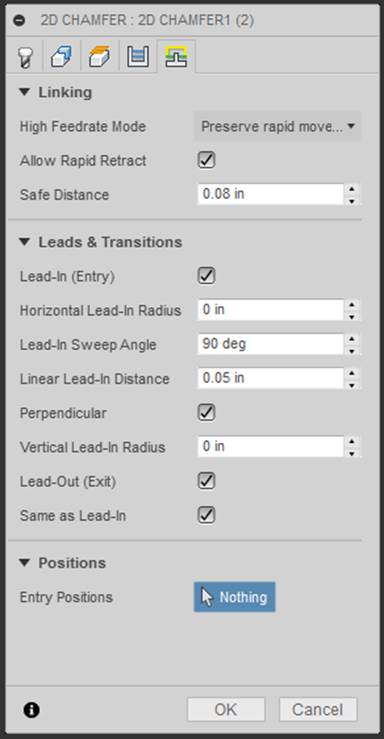
The following parameters were used and will be discussed in lab. For details as to what a particular item is, hover your mouse over the item.
Shaft Lathe Gage [Return to top]
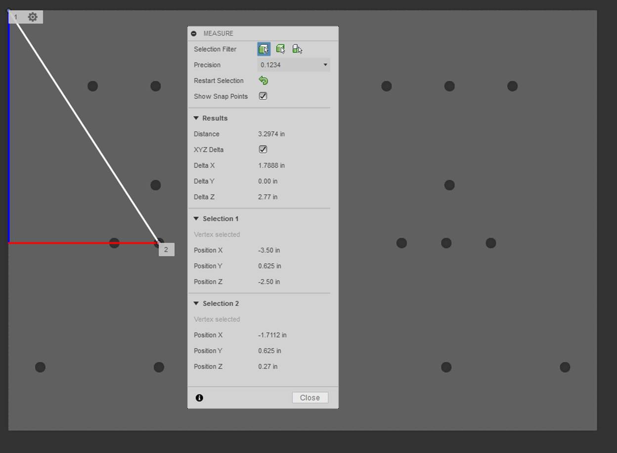
NOTE: It is imperative that you properly sketch the point location of the WCS
origin. Use “Inspect” in Fusion to measure the proper distance between a hole
on your part and the top left corner of the jig plate shown below. If “Show
Snap Points” is not enabled, you could be measuring from the edge of the hole.
Ensure that you properly measure from the center of the whole to the top
left corner. The X and Y distances will be used for dimensioning the point
location used for defining the WCS origin.
Shaft Lathe Gage Blank CAM
1.
Shaft Lathe Gage Blank CAM Part Setup
2.
Shaft Lathe Gage Blank Tool Setup
3.
Shaft Lathe Gage Blank Operation 1
a. Facing Operation
4.
Shaft Lathe Gage Blank Operation 2
a. Facing Operation
b. Drilling Operation
Blank Preparation
-
Consider minimum
stock removal
-
Consider material
needed to allow for facing bandsaw cut edge (surface on which accurate zero is
taken)
Dry Run Blank
-Refer
to the following video starting at 20:42 to see the Work Coordinate System
(WCS) offset for dry running the part in air
https://www.youtube.com/watch?v=Rh3cMfZzVno
Running Blank
-
Refer to the following video starting at 26:36 to return the WCS to the proper
height and run the program at the scaled back values
https://www.youtube.com/watch?v=Rh3cMfZzVno
Shaft Lathe Gage Contour CAM
1.
Shaft Lathe Gage Blank Operation 3
a. 2D Adaptive Operation
b. 2D Contour Operation
c. Chamfer Operation
2.
Shaft Lathe Gage Blank Operation 4
a. Chamfer Operation
Dry Run Shaft Lathe Gage Contour
-
Refer to the following video starting at 20:42 to see the Work Coordinate
System (WCS) offset for dry running the part in air
https://www.youtube.com/watch?v=Rh3cMfZzVno
Running Shaft Lathe Gage Contour
-
Refer to the following video starting at 26:36 to return the WCS to the proper
height and run the program at the scaled back values
https://www.youtube.com/watch?v=Rh3cMfZzVno
Example Speeds and Feeds Calculation [Return to top]
The following document links the comprehensive speeds and feeds document that should be followed during the manufacturing process. Listed below is a simple calculation for reference from the document.
Recommended Surface Speeds for Common
Materials
The table below contains a recommended surface speeds for common materials when using DML equipment. These values are conservative because our primary goal is fostering a safe learning environment (for our users and our tools!), not trying to squeeze every second out of each operation.
|
Material |
Recommended HSS Speed, V [surface ft/min] |
|
|
|
|
Aluminum and its alloys |
250 |
|
Bronze (high tensile) |
100 |
|
Cast Iron (soft) |
100 |
|
Cast Iron (medium hard) |
80 |
|
Cast Iron (hard chilled) |
20 |
|
Hastelloy |
20 |
|
Inconel |
25 |
|
Magnesium and its alloys |
300 |
|
Monel |
25 |
|
High nickel steel |
50 |
|
Mild steel (.2-.3 C) |
100 |
|
Steel (.4-.5 C) |
60 |
|
Tool steel |
40 |
|
Forgings |
40 |
|
Steel alloys (300-400 Brinell) |
30 |
|
Heat Treated Steels |
|
|
35-40 Rockwell C |
20 |
|
40-45 Rockwell C |
20 |
|
45-50 Rockwell C |
15 |
|
50-55 Rockwell C |
15 |
|
stainless steel free
machining |
40 |
|
stainless work hardening |
20 |
|
Titanium alloys |
20 |
|
|
|
|
* multiply surface speeds
in table by 2.5 for carbide cutting tools * |
|
Examples of Drilling and Milling Speeds and Feeds
Calculations
Example 1A: Calculate the speed and feed for a ¼″
HSS drill bit in mild steel on a manual milling machine in the lab.
First, lookup the recommended surface speed in Table 1 (V ≈ 100 ft/min) and calculate the spindle speed from Equation 2:
N [rpm] = 12 × V /
(π × D)
= 12
in/ft × 100 ft/min / (π × 0.25 in/rev)
≈ 1500
rpm
Next lookup the recommended feed per revolution for the drill bit in Table 2 (fr ≈ 0.004 in/rev) and calculate the feed rate using Equation 3:
f [in/min] = N [rpm] ×
fr [in/rev]
= 1500 rev/min × 0.004 in/rev
≈ 6.0 in/min
Note that these speed and feed values are guidelines assuming adequate (flooded) lubrication, workpiece stiffness and drill depth less than 3 drill diameters (0.75″). When applying oil manually (as in the lab), scale the feed and speed back to 60%, so N = 900 rpm and f = 3.6 in/min (final answer).
References:
[1]: http://help.autodesk.com/view/fusion360/ENU/?guid=GUID-E9EBAB0B-5DF4-4168-BA58-AEA055D980F5