PARTING ON THE LATHE
Introduction
Parting on
the lathe is simple operation in theory, but requires close attention to detail
for success. Failure to heed the
following tips can result in destroyed parting tools, ejection of the part from
the spindle, and permanent damage to the X-axis power feed on the lathe, so
when practicing, pay very close attention to what you are doing and have Mike
or a senior TA supervise the first time you try. For those who like to take notes as you read,
here’s
a condensed pdf version of this document.
Step 1: Part-off Tool Selection
As shown in
figure 1, there are generally two types of part-off or grooving tools: HSS and tungsten
carbide. As usual, HSS is cheaper,
tougher, and can be reground by hand once damaged. Carbide can tolerate much more heat, but once
the insert is damaged it must be replaced with a new one.
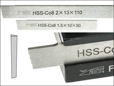
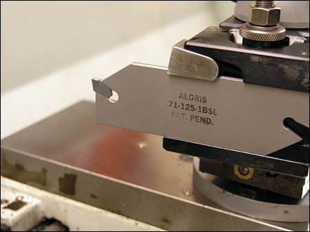
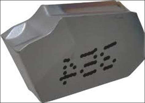
Figure 1:
HSS part-off tool (left) versus indexable part-off blade (center) and carbide
insert (right).
There are
many different styles of part-off inserts depending on the type of material
being cut and insert effectiveness. Most
styles are available in left hand, right hand, and neutral axial rakes
depending on where you want the inevitable little cylindrical “pip” to remain
(on the work clamped in the chuck or on the drop). In addition, carbide part-off inserts are
available with high temperature coatings for use cutting ferrous and abrasive
materials.
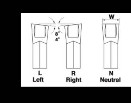
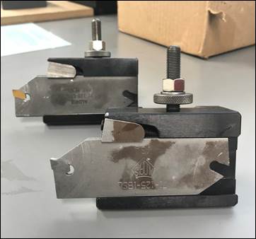
Figure 2: Carbide
parting inserts are available with different rake angles and coatings like titanium
nitride (TiN) for use cutting ferrous materials.
Step 2: Part-off Tool Inspection
Inspect the
parting tool closely before using. If
using HSS parting blades, grind and/or hone the cutting edge to ensure it’s
sharp. If using an indexable
part-off tool, check that the cutting insert is in good condition.
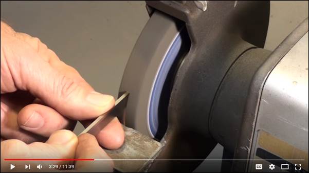
Figure 3:
Video on how to properly sharpen and use HSS parting blades.
Step 3: Maximize Cutting Tool
Stiffness.
Always
maximize cutting tool stiffness by minimizing the length the blade sticks out
beyond the toolholder block. For parting
larger diameters or stronger workpieces, it will be necessary to adjust the
stickout multiple times during the parting operation, as the tool cuts deeper
into the material. For the same reason,
always part-off as close to the chuck jaws as possible (typically within 1/8”)
to maximize part stiffness during parting, as illustrated in figure 7.
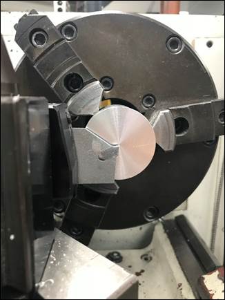
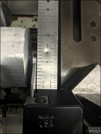
Figure 4:
Minimize the distance the part-off blade sticks out of the toolholder to
increase tool stiffness during parting.
Note the clearance between the toolholder and the part is also
minimized.
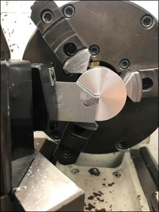
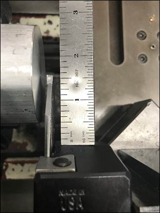
Figure 5:
Compared to Figure 4 the part-off blade is sticking out farther than necessary
for this 2” round stock, decreasing tool stiffness. The blade should be adjusted shorter.
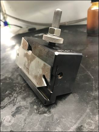
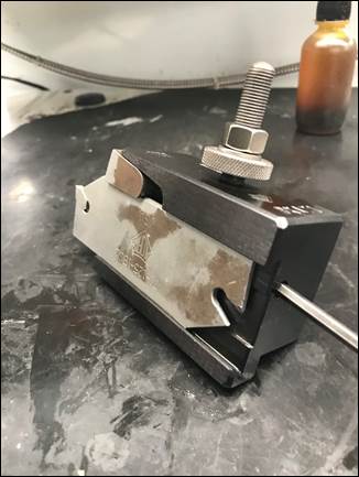
Figure 6: To
adjust the part-off blade length for a particular cutting depth, use an Allen
wrench to loosen the screw in the back of toolholder which loosens the wedge at
the front of the toolholder and allows the part-off blade to be repositioned at
a different length.
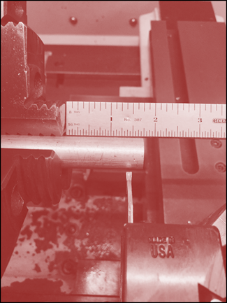
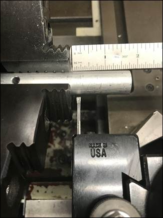
Figure 7: It
is better to perform part-off operations closer to the chuck (right) because of
the decreased deflection when parting. Within 1/8” of the chuck jaws is
preferable.
To function,
the part-off tool must be perfectly
aligned with the X-axis on the lathe.
This can be done several ways; the most common two are using a 1-2-3
block or a dial indicator, as shown in Figure 8.
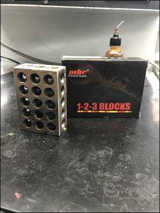
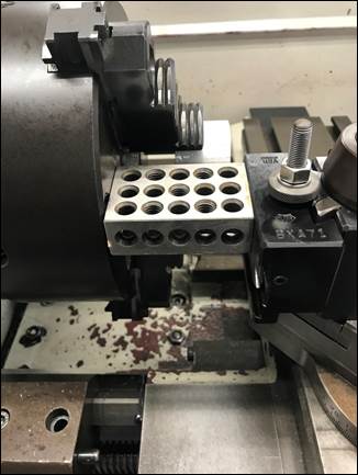
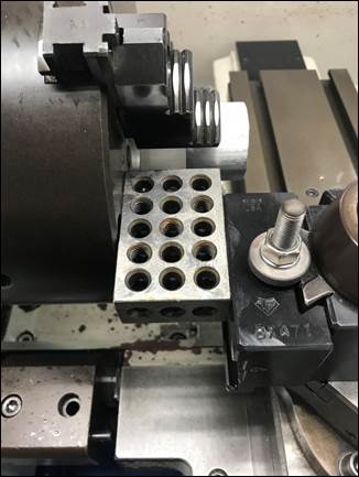
Figure 8: To
ensure the parting tool is perpendicular to the face of the chuck you can use a
1-2-3 block (whose surfaces are ground to be parallel to one another). Loosen the tool post, align the edge of the
toolholder flush with the 1-2-3 block, and re-tighten the tool post. Be careful to not drop the 1-2-3 block.
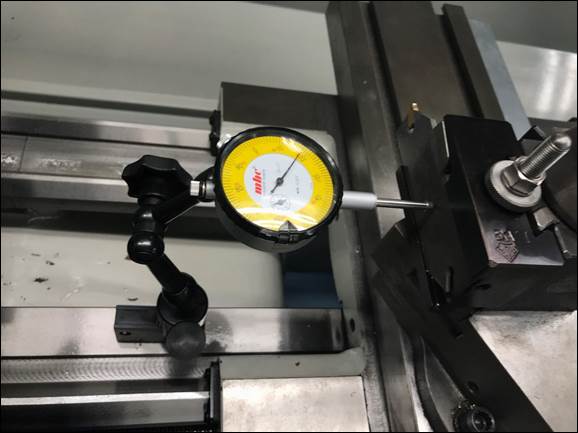
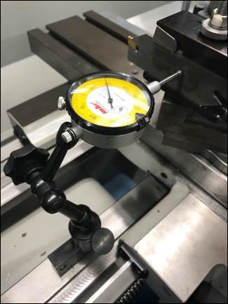
Figure 9: To
ensure the parting tool is perpendicular to the face of the chuck you can
alternatively use a dial indicator.
Attach the dial indicator to a Noga holder found in the metrology
cabinet, and place gently on the guideways (DO NOT slide the holder along the
guideway; simply set it down in place!)
Position the contact tip against the toolholder and move the cross slide
along the X-axis while checking to see the change on the indicator. +/- 0.001” over the length of the toolholder
or part-off blade is acceptable / desirable.
Step 5: Check and/or Set the
Vertical Height of the Tool
Like all
tools used on the lathe, the part-off tool height must be checked and adjusted
so it is as close to the vertical spindle centerline as possible. Never assume the tool is setup properly just
because it was in the lathe cabinet for the machine you’re using! If the parting tool is not on vertical
centerline it will fail to cut properly, and will be damaged in use.
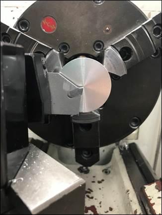
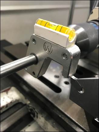
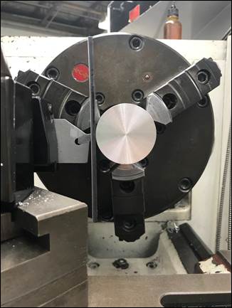
Figure 10:
Just like the turning/facing tool, the parting tool has to on the vertical
centerline using the lathe gage (bubble level) or ruler technique.
Step 6: Feed by Hand with Lots of
Oil
When
parting on a manual lathe, NEVER use the automatic feed
(because you can’t feel poor chip evacuation like you can by hand), and be sure to use lots of oil because the
parting process has a wide width of cut and generates a LOT of heat. For this reason, the part will also be VERY
hot after parting.
Like
drilling, use pecks to break up the chips and apply more oil to the tip of the
parting tool.
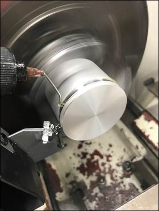
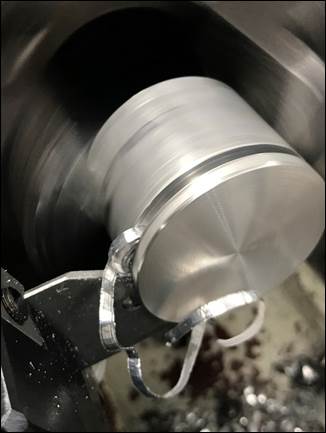
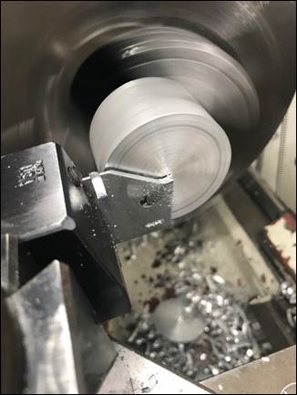
Figure 11:
Ensure that throughout the cut oil is being used to reduce the heat in the
cutting zone (left), if the chip starts to coil or “crunch”, back out of the
cut then reengage the workpiece. This
should break the chip (center). The parting
tool should leave a fairly smooth surface finish (right).
Part-off Surface Speed
When parting
on a manual machine, the parting tool should generally be run at approximately
60% of the recommended surface speed for the same workpiece/cutting tool
materials (like all manual machining operations). The Feeds
and Speeds resource document has an example of parting that will be
repeated here for convenience:
Calculate the speeds for
parting off 1” diameter aluminum and 1” diameter mild steel workpieces on the
lathe using a standard carbide part-off inserts.
First, lookup the recommended
surface speeds in Table
1 for a HSS part-off tool (VALUM
≈ 250 ft/min, VSTEEL
≈ 100 ft/min). It’s often better
to use the HSS value even when parting with carbide inserts on a manual machine
because parting is a problematic operation for inexperienced users.
Next, calculate the spindle
speeds:
NALUM [rpm] = 12 × V / (π ×
D)
= 12 in/ft × 250 ft/min / (π × 1 in/rev)
≈ 950 rpm
NSTEEL [rpm] = 12 × V / (π ×
D)
= 12 in/ft × 100 ft/min / (π × 1 in/rev)
≈ 380 rpm
Note: since applying oil
manually, scale the speeds back to 60%, so NALUM ≈ 570 rpm and
NSTEEL ≈ 230 rpm (final
answer). Note these are MAXIMUM
values and lathe chuck safety must take precedence; spinning the lathe chuck at
570 rpm is about the upper limit of what we safely do in the lab, so for
smaller workpieces, do not exceed 600 rpm, regardless of the calculation
results.
Catching Parts
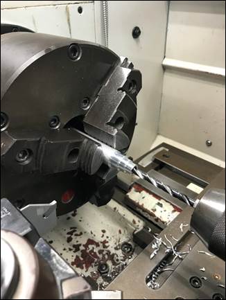
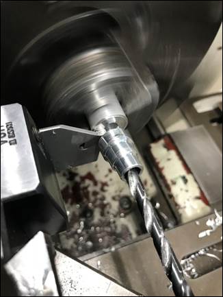
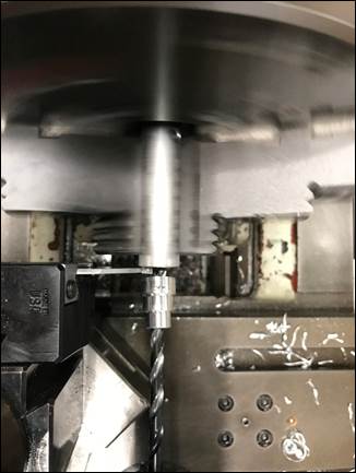
Figure 12:
Parts with thru-holes can be safety caught using an undersized drill bit. NEVER try to catch a part by hand! Be careful not to run the part-off tool into
the drill bit. If there is no hole in
the part, place a rag under the part to soften its landing.
Here is a good video on parting tool
basics using HSS blades.