THREADING ON THE LATHE
Introduction
This
document presents some of the more common techniques for threading on the
manual engine lathe.
Using a tap
handle is the most common method of tapping on the lathe. The workpiece is clamped in the lathe chuck,
a spring
loaded center (for smaller taps) or a dead
center (for larger taps) is clamped in the tailstock, and the tap is held
and rotated using a tap handle, as we do with the assigned parts in lab.
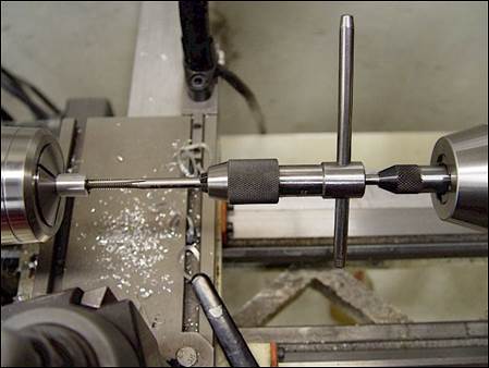
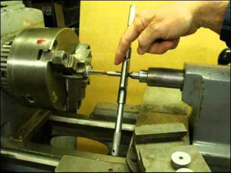
Figure 1a:
Examples of using standard tap wrenches and spring loaded tap guide (left) or
dead center (right) to tap holes on the lathe.
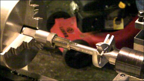
Figure 1b:
Example of using an adjustable wrench and a live center to tap holes on the
lathe.
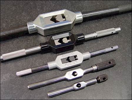
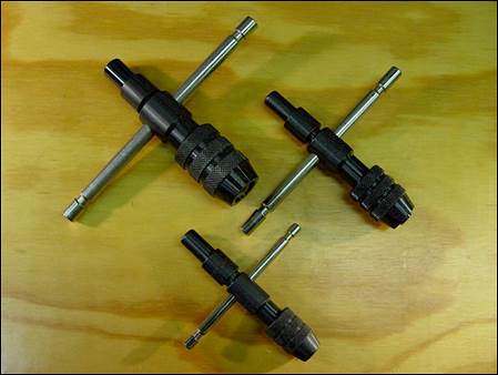
Figure 1c: Examples
of various tap handles.
Using a die
handle is a common method of external thread cutting on the lathe. The workpiece is clamped in the lathe chuck,
and the threading die is held and rotated using a die handle.
In
general, round-shaped dies are for cutting threads onto a workpiece and
hex-shaped dies are for chasing (cleaning up / repairing) existing threads.
Before
using a threading die it’s important to make sure the major diameter of the shaft
to be threaded matches the range listed in the Machinery Handbook. For example, a ½-20 UNF 2A thread must have a
major diameter between 0.4906 and 0.4987”.
The smaller the major diameter, the easier the die will cut. In general, undersize the shaft diameter by
2% of the major thread diameter.
When
using a threading die on the lathe it’s important to start the thread die
collinear to the axis of the part, so use the body of the drill chuck for
alignment and guidance. It’s also
important to cut a generous chamfer on the end of the part to help the
threading die start cutting.
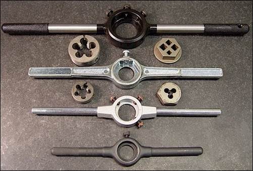
Figure 2a:
Examples of various threading die handles.
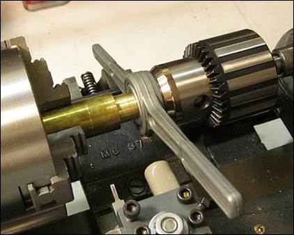
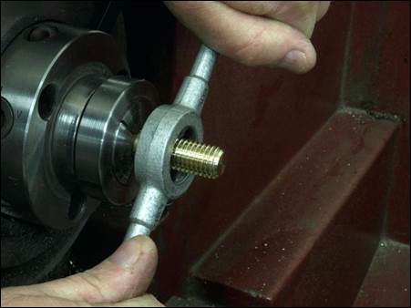
Figure 2b:
Using the drill chuck body to align the threading die axis with the workpiece
axis when starting the thread.
Rigid
tapping is the second most common method of thread cutting on the lathe. With this technique the tap or die is clamped
in the tailstock using a variety of methods and threaded into or onto the
workpiece under spindle power. Smaller
taps up to 3/8” can be clamped in a keyed Jacob’s style chuck (NEVER a keyless chuck!). Larger taps should be clamped using a split
sleeve or heavy duty tap driver, as shown in figure 3b.
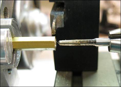
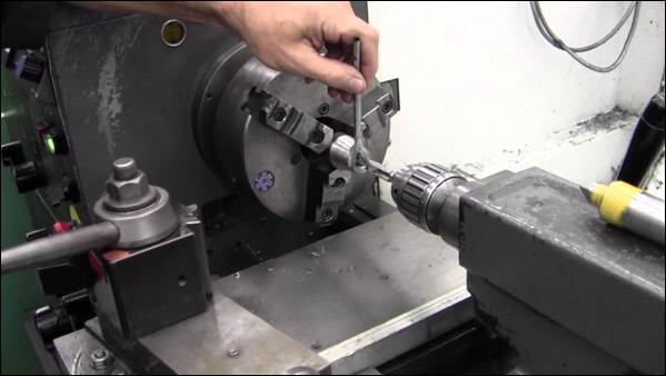
Figure 3a:
Rigid tapping on manual lathe. Click the
image on the right for a
video showing the process.
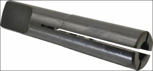
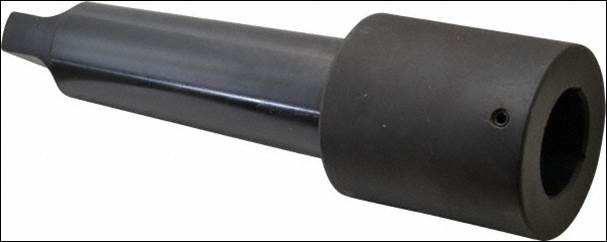
Figure 3b: Example
of split sleeve tap driver for lathe tailstock (left) and heavy duty tap driver
for lathe tailstock (right).
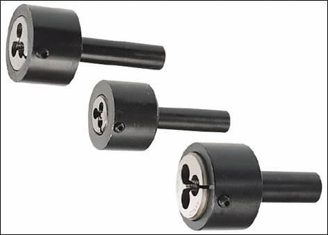
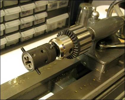
Figure 3c:
Rigid die cutting on manual lathe.
Die cutting
video
Single point
threading involves mounting a threading tool with the proper thread profile to the
toolpost and cutting the thread using multiple synchronized passes.
In general
there are two types of cutting tool geometries which can be used: partial and
full form profiles. Partial profile
cutting geometries only cut the minor (or root) diameter of the thread, whereas
full profile cutting geometries cut both the minor and major diameters of the
thread profile to size. The advantage of
partial profile cutting geometries is that one tool can cut a variety of thread
pitches, whereas a full profile cutting geometry is only good for one
particular thread pitch. The advantage
of full profile cutting geometries is that the entire thread is finished in one
operation, saving significant thread finishing and deburring time.
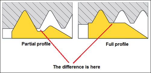
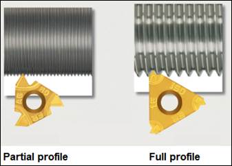
Figure 4a:
Partial vs full form profile threading geometries.
The
following videos explain the process in good detail. Fast forward through the parts which are not
interesting to you J.
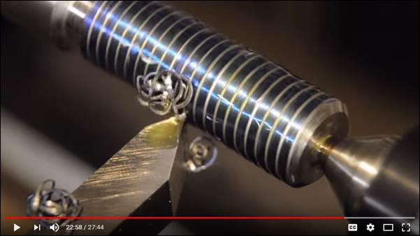
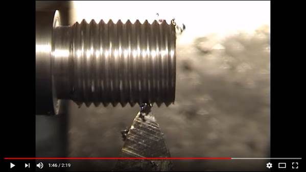
Figure 4b:
Good single point threading video (left; threading starts at 18:08 time stamp)
and shorter clip of thread cutting (right).
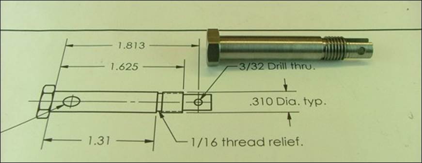
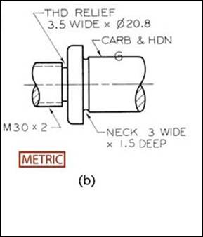
Figure 4c:
Examples of properly designed thread reliefs.
The process
for single point turning threads in the design lab is as follows:
1.
Clamp the
part in the lathe using a live center if necessary.
2.
Turn the OD
to the target major diameter and include a chamfer on the end at least 0.020”
smaller than the minor diameter of the thread profile to be cut.
3.
If
permissible, cut a thread relief using a grooving tool (as shown in Figure 10
and the two video thumbnail images above).
The thread relief should be slightly less than the minor thread
diameter.
4.
Adjust the
gearbox levers on the front of the headstock to cut the proper thread pitch.
5.
Adjust the
threading tool so
it is aligned parallel to the X-axis.
6.
Touch off on
the part and zero the X-axis.
7.
Cut a light
(0.001 - 0.002”) scratch pass across the surface of the part to be checked with
a thread gage for accuracy.
8.
If the pitch
of the scratch pass measures correctly, begin cutting the thread to depth;
start with deeper depths of cut (.010” in aluminum, 0.005” in steel) and make
progressively shallower cuts as the thread gets deeper and the threading tool
begins to leave a worse finish)
9.
As you approach
final thread size, use a fine file to carefully debur the rough edges of the
major diameter (unless using a full profile insert, which deburrs the major
diameters automatically, as discussed above).
The major diameter should end up a few thousandths of an inch under the
nominal size, according to the tolerances listed in the Machinery Handbook
(e.g. 0.4906-0.4987” for a ½-20 UNF 2A thread).
You will know when you are close to the final size by keeping track of
your X-infeed value, which will end up smaller than the equivalent internal
thread’s minimum minor diameter by the noted allowance (e.g. 0.446” – 0.0013” =
0.4447” for the same ½-20 UNF 2A thread).
10. The procedure for making an actual cut is:
a.
Check the
direction of the threading direction by engaging the half-nut with the tool a
safe distance from the part; for this example, we will thread toward the chuck
b.
Adjust the
spindle speed to a low setting (100-300 rpm) depending on how brave you are J
c.
Position the
tool in a safe starting location to begin cutting the thread
d.
Advance the
tool toward the part the distance (depth of cut) you wish to cut
e.
Engage the
half-nut for threading (it’s safest to leave this engaged for the duration of
the threading session)
f.
Turn the
spindle ON in the FWD direction and allow the tool to make a cut
g.
Turn the
spindle OFF before the tool reaches a shoulder (if not exists); you can use the
foot brake to stop it quickly if needed; if you stop too early, simply bump the
power switch to continue the cut or rotate the chuck by hand
h.
Retract the
tool a safe distance from the part in the X-direction
i.
Turn the
spindle ON in the REV direction to allow the tool to return to a safe starting
location
j.
Repeat steps
d. thru i. until the desired minor or pitch diameter is reached.
Figure 4d: Insert comprehensive single point
threading video here?
Threads can
be measured at least three different ways: by checking with a mating nut or
thread gage, by using a dedicated thread micrometer, or by using the three wire
method.
Mating Nut or Thread Gage
Checking
with a mating quality nut or thread gage is the easiest method to determine
when the thread is cut deep enough. Nuts
are much cheaper than calibrated thread
gages, but work fine for most prototyping applications.
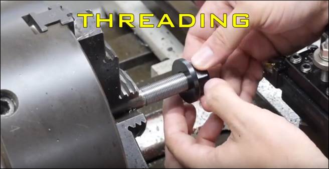
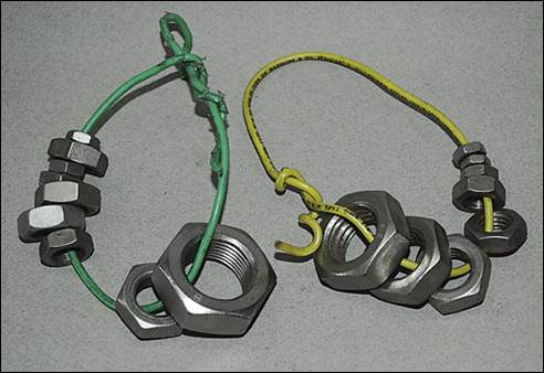
Figure 5a:
Checking thread size using an existing, quality nut. It’s convenient to keep a complete set of
quality nuts on rings for thread measurement (right).
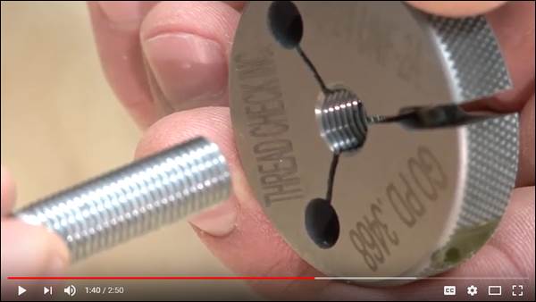
Figure 5b:
Checking thread size using a thread gage.
Click
the thumbnail for the video.
Thread Micrometer
Using a
thread micrometer is the easiest way to accurately measure thread pitch
diameter for comparison to the thread data listed in the Machinery Handbook or this link. However, thread mics are fairly expensive.
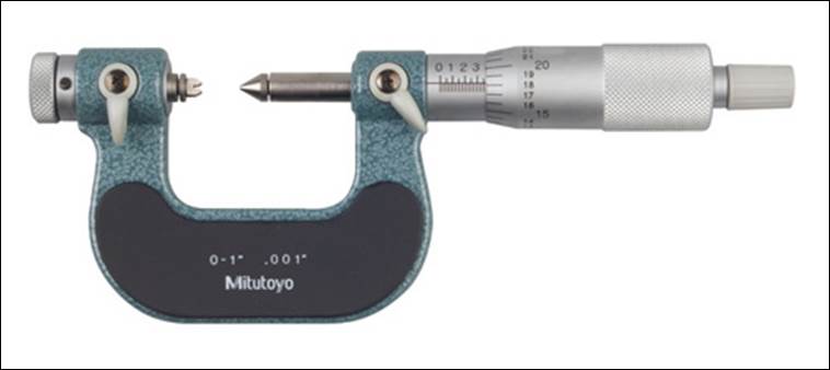
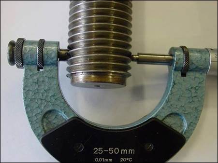
Figure 6a:
Example of a thread micrometer (notice the v-shaped anvils) and its use
measuring thread pitch diameter.
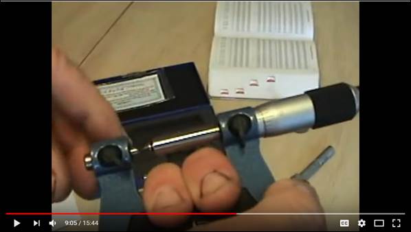
Figure 6b:
(Poorly made) video on how to use a thread micrometer. Click
thumbnail for video.
3 Wire Method
The three
wire method uses basic geometry and three identically sized wire rods to allow
the pitch diameter to be calculated using any standard micrometer
measurement. The three wire method is
very accurate and the cheapest method of measuring a variety of thread pitch
diameters. The downside to this method
is that it requires a lot of dexterity to make an accurate measurement without
dropping the precision thread wires.
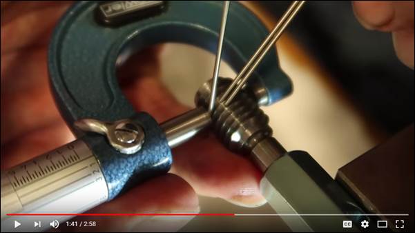
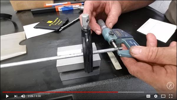
Figure 7a:
Checking thread size using 3 wire method. Click the thumbnails for the videos.
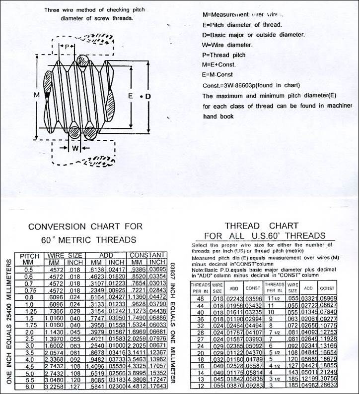
Figure 7b: Thread
wire formulas for converting between actual measurement and pitch diameter.
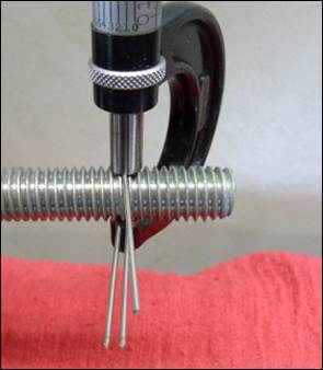
Figure 7c:
Three wire measurement method explained.
Click
image for .pdf file.
Miscellaneous Points
Always
use cutting oil when threading on the lathe.
WD40 works well for aluminum. Oatey dark
threading oil works well for steel.
Chlorinated Moly-D works best for materials which are tougher to
machine, like stainless and alloy steels.