BORING ON THE MILL
Introduction
Boring on
the mill is a simple operation in theory, but requires close attention to
detail for success when precision is important (i.e. to within 0.001” of target
size).
*** CAUTION ***
Please
understand that using a boring head on a milling machine is an inherently
dangerous process because the tool is deceptively dangerous when rotating, so YOU MUST KEEP YOUR HANDS AWAY FROM THE
CUTTING ZONE AT ALL TIMES WHEN THE MILL IS RUNNING.
Step 0: Understand EVERYTHING
Matters
Using a
boring bar to simply enlarge an existing hole is a straightforward
process. However, when trying to hit a
particular size and tight tolerance, everything begins to matter: boring bar
selection and setup, cutting edge geometry, tool deflection, lubrication,
cutting parameters, chip evacuation, part temperature, and our ability to
measure the bore accurately and precisely.
If you cannot force yourself to be a little OCD, you might not be good
at precision boring J.
Step 1: Boring Bar Selection
There are
three general types of boring bars: high speed steel, brazed carbide, and indexable carbide.
The benefits of HSS are that it is cheaper and tougher. The benefits of carbide are that it can
tolerate much more heat (i.e. it can cut 2.5 – 5 times faster than HSS), and it
has a modulus of rigidity that is about 2.5 times greater than steel.
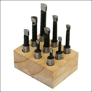
Figure 1:
Examples of HSS boring bars.
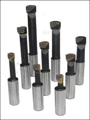
Figure 2:
Example of brazed carbide boring bars, where a small piece of tungsten carbide
is brazed onto a cheaper steel shank.
When the carbide chips, the boring bar is either reground (which is
difficult to do well) or discarded.
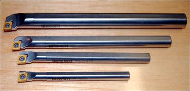
Figure 3:
Example of indexable carbide boring bars, where a
replaceable tungsten carbide insert is attached to a machined pocket in a steel
or carbide boring bar shank. When the
carbide insert chips, it can be easily and quickly
rotated to another corner (indexed) or replaced with another insert.
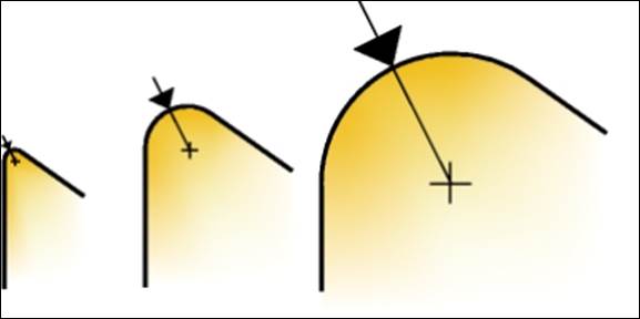
Figure 4: Larger
corner radii are stronger and better for roughing, but smaller corner radii
typically produce more accurate bore sizes and better surface finishes (at
reduced feeds).
As with all
metal cutting processes, stiffness is key when boring,
so do everything you can to maximize it: use the largest diameter boring bar
and the shortest clamping length possible.
Step 2: Boring Bar Setup
It’s worth
repeating: as with all metal cutting processes, stiffness is key when boring,
so do everything you can to maximize it: use the largest diameter boring bar
and the shortest clamping length possible.
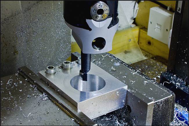
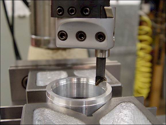
Figure 5:
Example of properly selected brazed carbide boring bars. Notice how short and stiff the selected bars
are in relation to the respective workpieces.
Many boring
bars do not have alignment flats on them, so it is necessary to orient the top
(flat) surface of the cutting edge so it passes through the centerline of the
spindle axis, as shown in figure 6. This
orientation is referred to as a neutral rake angle and is the safest for most
materials and the only orientation that works properly when using these types
of boring bars in a boring head. When
setting a boring bar with no alignment flats, it is always necessary to perform
a test cut to ensure the rake angle is set properly.
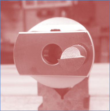
Figure 6:
Examples of possible boring bar orientations (negative (left), neutral
(center), and positive rake (right)).
ALWAYS use neutral orientation (center) in a boring head on a mill.
When setting
up the workpiece, always ensure adequate clearance exists beneath it and the
vise if boring a thru hole. Whether
boring a thru or blind hole, always set the quill depth stop appropriately to
prevent an over-travel condition, which would damage the part, the boring head,
and potentially the vise.
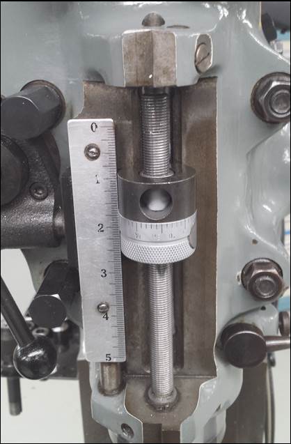
Figure 7: Set the quill depth stop before using the boring head.
Step 3: Selection of Cutting
Parameters
When using a
boring head on a milling machine, it’s best to begin with a cutting speed equal
to half the typical computed value and work your way up if vibration and tool
life allow it. The primary reasons are
the reduced stiffness due to the cantilevered nature of boring bars, as well as
the difficulty of providing consistent lubrication to, and chip evaluation
from, the cutting edge of the tool unless flood cooling, as in a CNC mill. For safety reasons due to the rotational
imbalance inherent in a boring head, never rotate the boring head faster than
600 rpm in the design lab.
Boring heads
on Bridgeport-size milling machines should usually not be used with depth cuts
deeper than 0.020”. It’s important to
understand there is also a safe minimum
depth of cut, below which the tool constantly transitions between cutting and
smearing, leaving a very inconsistent size and finish. This safe minimum depth of cut is typically
around 0.003” to 0.005” depending on the material. Harder / stronger materials can usually
tolerate a smaller minimum depth of cut, as can boring
bars with sharp corners.
When making
depth adjustments, you can use the calibrated dial on the boring head, or a
dial indicator if trying to be as precise as possible, or using a worn boring
head.
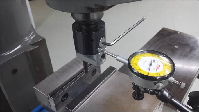
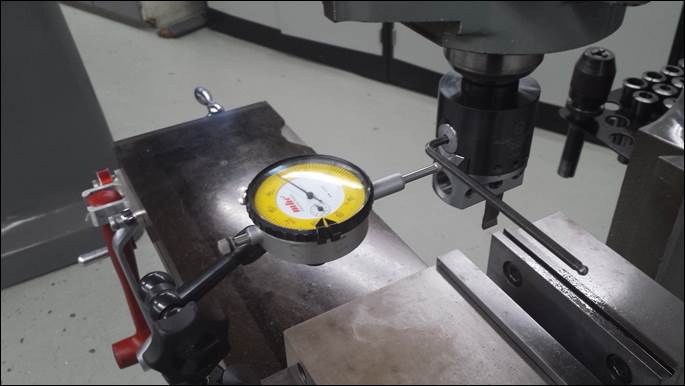
Figure 8:
Example of using a dial indicator to adjust the boring head depth of cut. This isn’t always necessary, but it
facilitates more accurate adjustments.
Step 4: Bridgeport Automatic
Quill Feed
Bridgeport
milling machines have three choices for quill automatic quill feedrate: 0.001,
0.003, and 0.006 in/rev. The middle
speed typically works well for most work.
The
following schematic and accompanying video explain the function of the
automatic feed.
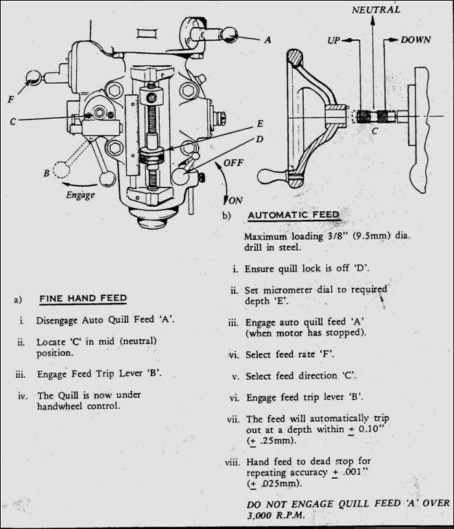
Figure 9:
Bridgeport automatic quill feed explained.
Click for
short video illustrating its use.
Step 5: Ideology for Repeatable
Results
Consistency
is crucial to obtaining repeatable results when using boring heads. Meaning, you want to vary the fewest
parameters possible during each cut, and preferably only one at a time. Anything that affects the cutting force at
the tool tip will change the amount of material removed, or the surface finish
obtained: depth of cut, feedrate, lubrication, corner radius, part temperature,
etcetera.
Let’s say you are trying to thru-bore a 1” hole in a
piece of 303 stainless steel. One approach would be as follows:
1.
Remove as
much material as possible by drilling, since it’s the most efficient method of
material removal. When doing this, be
sure to leave enough stock for the next step.
Leave the bore about 0.050” small in this case.
2.
Perform a
few test cuts to check how the boring bar is cutting. Rarely will a boring bar cut perfectly. If you try to remove 0.010” off the diameter
of the bore, it may only remove 0.0096” on the first pass and another 0.0004”
on the spring pass. (A spring pass is
simply a second pass that helps compensate for tool or part deflection during
the first pass.) It’s important to make a couple passes and write down how much each
removes so you can take the average and know what to expect when it matters.
3.
Do not try
to “sneak up” on the final size. As
anti-intuitive as it may sound, the best results are not obtained by making
smaller and smaller cuts until you reach the desired size because of the safe
minimum depth of cut discussed in Step 3 above.
The best results are obtained by repeatedly removing a similar amount of
material on each pass and using the resulting measurement data to make small
adjustments to each subsequent pass. On
the 1” 303 example piece, the final cut would remove 0.005” to 0.010” from the
diameter to bring the part into final size tolerance.
Step 6: Bore Measurement
Bore
measurements can be made using several tools, depending on the budget, operator
skill, and required measurement accuracy.
Dial or Digital Calipers
The easiest
tool to use for bore measurement is also the least accurate: dial
calipers. These typically aren’t very
accurate (within a couple thousandths of an inch) on smaller bores because the
inside jaws have flats ground into them that prevent them from measuring the
true size of the hole.
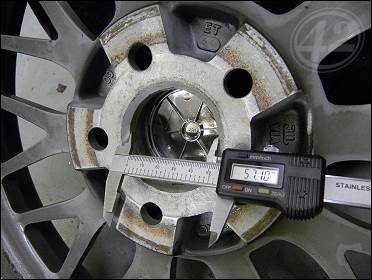
Figure 10:
Measuring larger bores with dial or digital calipers.
Inside Micrometers
The second
easiest tool to use is an inside micrometer.
However, inside mics typically only work well for measuring shallow
bores up to approximately 3” in diameter.
They are accurate to +/-0.001”.
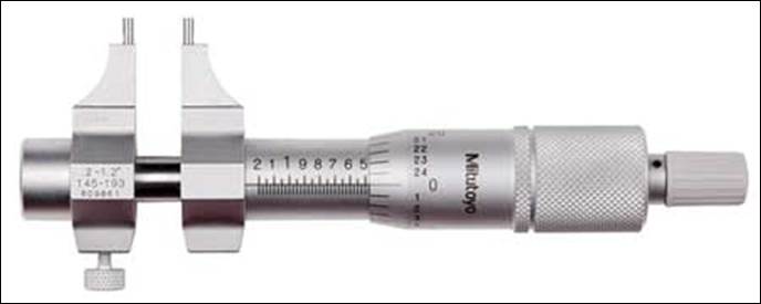
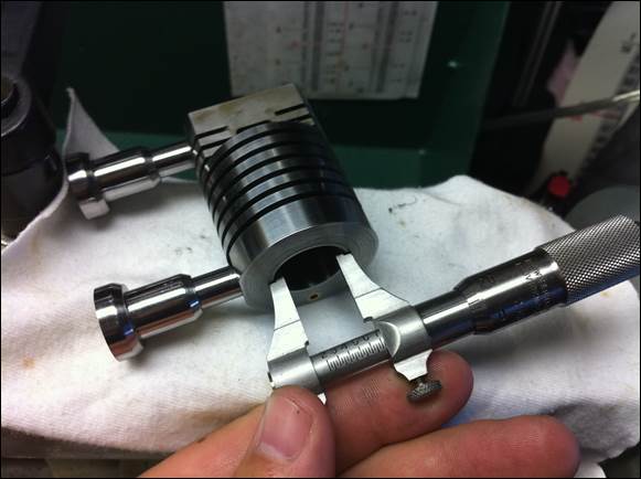
Figure 11:
Inside micrometers used to measure a precision bore.
Small Hole Gages
Next are
small hole gages, which are also inserted into a bore
until a small amount of drag is felt and subsequently measured with outside
mics. Used in sensitive hands, small
gages are accurate to +/-0.002”.
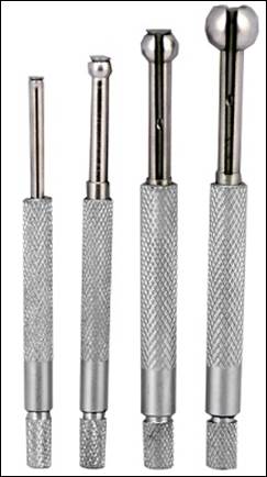
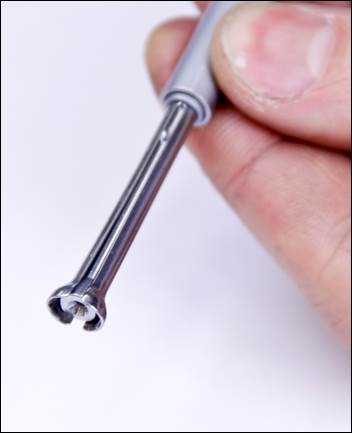
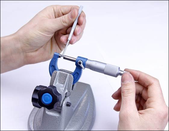
Figure 12:
Example of small hole gages.
Gage Pins
Gage pins
are another way to measure precision holes.
Gage pins are available in virtually any size and typically manufactured
(precision ground) to +/-0.0002” tolerance.
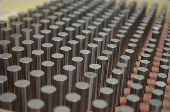
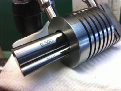
Figure 13:
Gage pin assortment used to measure precision bores.
Telescoping Gages
Telescoping
gages are commonly used to measure bores, but require a lot of operator skill
to provide repeatable and accurate results.
After being inserted into the bore, a small amount of torque is applied
to a friction lock, the telescoping gage is swept
through the center of the bore, and subsequently measured with a
micrometer. The challenge is applying
the proper amount of torque to the friction lock, as too little results in the
gage not holding the true bore reading once removed, and too much
results in the gage distorting and showing a reading that is larger than
the actual bore size. Like all metrology
tools, practicing on a bore of known size (like a bearing race for example) is
the only way to become proficient in the use of telescoping gages. Used in sensitive hands, telescoping bore
gages are accurate to around +/- 0.0015.
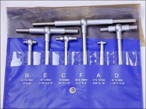
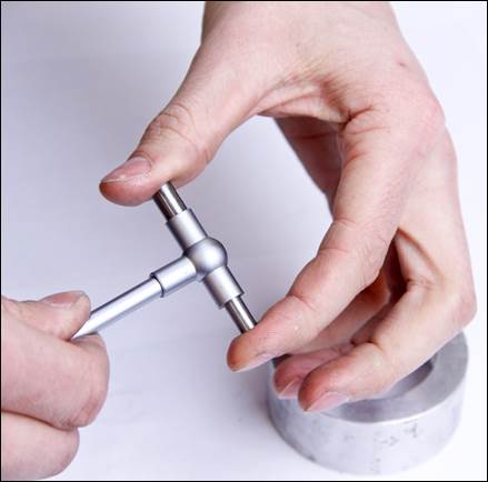
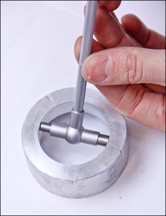
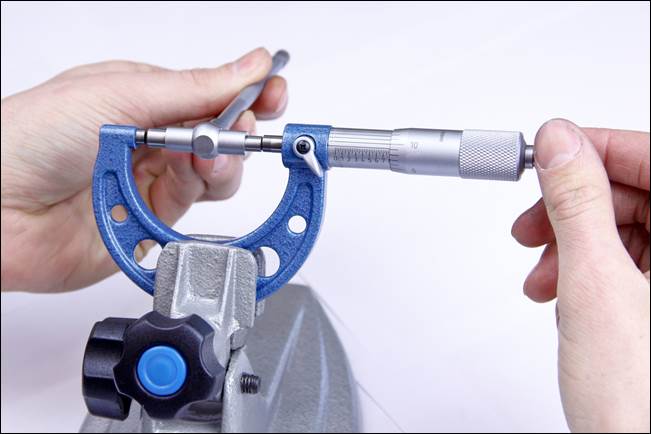
Figure: 14:
Using telescoping gages and outside mics to measure bore diameters.
Bore Gages
Bore gages
are essentially precision telescoping gages with dial indicators built in. In use they are first calibrated using an
outside micrometer and then the actual bore size is measured relative to that
calibration using the dial indicator . Bore gages are accurate to +/-0.0005”.
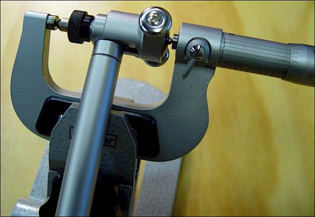
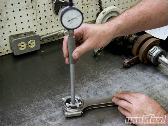
Figure 15:
Bore gage used to measure the bearing diameter of a connecting rod for an
automobile engine.
3 Point Micrometers
The best
tool for accurately measuring bores is a 3 point internal micrometer; however,
these are also the most expensive option because each has a limited measurement
range, so several units have to be purchased to cover a decent range of
sizes. 3 point micrometers are accurate
to +/-0.00005” to +/-0.0001”.
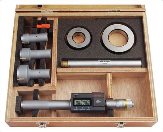
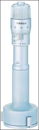
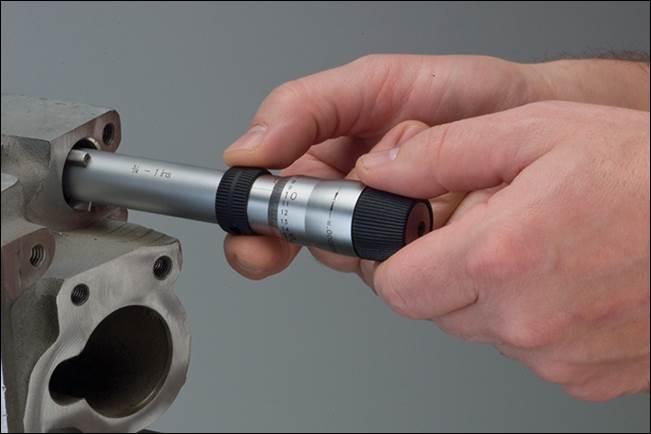
Figure 16: 3
Point Bore Micrometers.
Miscellaneous Tips