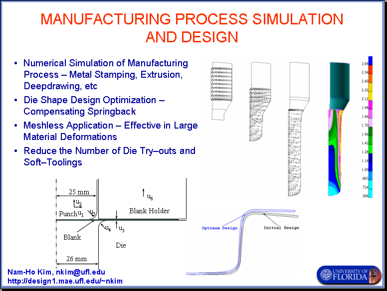

Many structural parts are fabricated through stamping, extrusion, or deepdrawing processes. Such manufacturing processes include very complicated mechanical phenomena including large deformation, change of the material status, friction, etc. In many commercial CAE programs use explicit time integration method in order to simulate such a complicated problems. However, the results from the explicit method is dubious because it does not perform any convergence iteration. On the other hand, the implicit method experiences difficulty in such a problem due to significant nonlinearities in volved in the simulation. In this research activity, the deepdrawing and extrusion processes are simulated using implicit meshfree method.
In addition to the simulation, a die shape design sensitivity analysis and optimization is proposed in which the performance function of the manufacturing process can be optimized by changing the die shape design parameters. The sensitivity calculation is extremely efficient such that sensitivity cost is less than 20% of the simulation cost.
A 2D deepdrawing process is modeled as shown in Fig. 1. Due to symmetry only half of the model is solved in the plane strain problem. The blank is modeled with 303 meshfree particles, while other parts are assumed a rigid body. The die and the blank holder are fixed in position such that initial compressive force is applied to the blank. The punch moves down vertically up to 30 mm. This position is called the maximum deformation. After that the punch and the blank are removed to simulate spring-back.\

Technically, large-deformation elasto-plastic material model is used in which the deformation gradient is multiplicatively decomposed into elastic and plastic parts. The modified Coulmb friction model is used in simulating contact between blank and other parts. Figure 2 shows the deformed geometry of the black at the maximum deformation and after spring-back. In the optimization section below, the spring-back will be compensated by changing design parameters.
A slave-master concept is used for the contact problem to impose a penalty regularization. The rigid surfaces (punch, draw die, and blank holder) are modeled as piecewise linear master segments. Using linear discretization, a very simple expression can be obtained, since the normal and tangential vectors on the contact surface remain constant. However, the possibility exists of a convergence problem at the kinked corners of adjacent linear master segments. A line search algorithm is used when the convergence problem occurs. The contact search is carried out for particles on the domain boundary. If penetration into the rigid surface is detected, then a penalty is imposed. Stick/slip conditions are determined by measuring the amount of motion relative to two adjacent configurations.

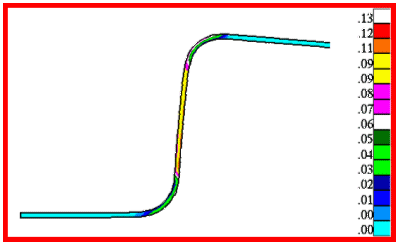
Figure 3 provides a contour plot of effective plastic strain at the moment of its final configuration. High plastic strain distribution is observed in the vertical section. A design constraint will be imposed for the maximum allowable amount of plastic strain to prevent material failure due to excessive plastic deformation. The maximum allowable amount of effective plastic strain is assumed to be 0.2.
The first two design parameters control the horizontal and vertical position of the punch. Horizontal movement is very important since it controls the gap between punch and draw die. The third and fourth parameters are round radii of the punch and draw die corners. A sharp corner may increase the plastic strain while reducing the amount of springback. The fifth parameter changes the thickness of the blank, which involves changes in the workpiece¡¯s shape. The sixth parameter controls the gap between the blank holder and die and allows the frictional force on the blank to be changed.
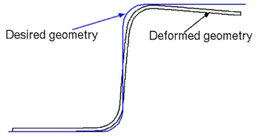
Sensitivity analysis calculates the gradients of the performance functions with respect to the design paraters. Since compensating spring-back is the the main purpose, it is necessary to define the spring-back as a performance function. Figure 4 shows the difference between the deformed geoemtry and the desired geometry. Thus, the difference between two geometries is defined as a performance function. In addition, the plastic strain is an important criterion in drawing process, is it also selected as a performance function.
Since the nonlinear problem is path-dependent, the sensitivity problem must be solved at each load step. However, it is unnecessary to follow the convergence iteration. Thus, still sensitivity calculation is very efficient compared to solving the structural problem.
The accuracy of DSA can be compared with the finite difference result by slightly perturbing the design and re-solving the same structural problem. The continuum-based design sensitivity method yields very accurate and efficient results. Table 1 compares the accuracy of the proposed sensitivity of various performance measures and with excellent agreements. A very small perturbation (= 10–6) is used for finite difference results.
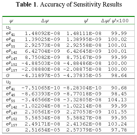
In Table 1, the design sensitivity of performance G does not agree as much as other performance measures. The reason is that the magnitude of the performance change is large compared to the other performance measures. For example, the sensitivity of G is 103 times larger than the other performance measures for u6. Thus, the finite difference method contains a large approximation error. This error will be reduced if perturbation size is decreased, although this may result in other performance measure inaccuracies due to numerical error. In short, it is very difficult to choose an appropriate perturbation size using the finite difference method.
As mentioned before, the design optimization problem is formulated to
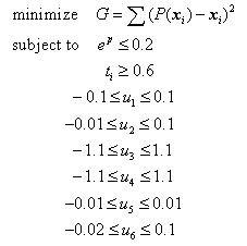
where P(x) is the orthogonally projected position of the particle x on the desired final workpiece shape, and t is thickness of the workpiece. Figure 4 illustrates the difference between desired and deformed geometry after springback. Design constraints are imposed to limit the amount of effective plastic strain that may result in material failure or severe necking. The minimum thickness of the each section is also limited. Limits on ui are established according to workpiece geometry and kinematics. Since ui's represent structure's relative movements, the initial values are set at zero.
The design optimization problem is solved using the sequential quadratic programming method in DOT by supplying meshfree analysis results and design sensitivity information. At each iteration, the initial geometry of the problem is updated.
The design optimization problem is converged in four iterations, which is quite fast considering the degree of nonlinearity involved in the structural analysis. The cost function, which is the difference between a desired shape and the deformed shape after springback, is reduced up to 24% of the initial design. All constraints are satisfied with no active constraint at the optimal design. The corner radius (u4) of the rigid die is significantly increased in order to reduce over-deflection of the workpiece at the binder part. The corner radius (u3) of the punch is decreased do that the workpiece remains vertical. It is interesting to note that the binder force, which is controlled by u6, is decreased from the initial design, which in turn reduces the frictional force.
The deformed shapes of the initial and optimal designs are shown in Figure 5. Over-deflection of the initial design around the blank holder area is significantly reduced in order to match the desired shape shown in Fig. 4. The vertical slope is also improved as compared to the initial design. However, it turns out that making a 90-degree vertical slope is very difficult based on current manufacturing processes unless a spring-forward method is used, which is not possible for this particular deepdrawing process. Note that the radius of the bottom corner is increased in the optimum design. Nevertheless, an effort to compensate for this region will result in a larger deviation from the desired shape in other regions.

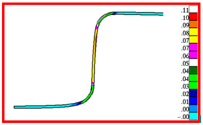
Figure 6 shows the effective plastic strain distribution at the optimal design. The maximum level of effective plastic strain at optimum design point is 12% less than that of the initial design and the amount of springback is also reduced.
In the deepdrawing process, a necking amount proportonal to the plastic deformation is an important criterion in determining the quality of the product. The necking amount is measured according to the change of thickness of the blank. Figure 7 shows thickness reductions for the initial and optimal designs. It is clear that the optimum design shows less plastic deformation compared to the initial design, which is consistent with the effective plastic strain distribution in Fig. 6. Since the plastic deformation is volume conserving, the area of the graph is transformed into an increase of the blank's cord length. The area of initial design in Fig. 7 is 1.18mm2, while it is 0.716 mm2 for the optimal design.
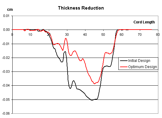
An initial cord length of 75mm is stretched during simulation to 76.46mm, while the total cord length is 75.87mm in optimal design, which is consistent with a reduction of plastic defor-mation in the optimum design. Figure 6 provides parallel results using a change of cord lengths for initial and optimal design models.