Conventional geometric representation and shape optimization of a solid structure has been based on the Lagrangian approach in which the structural domain and boundary changes according to shape design parameters. Such geometric details as fillet surfaces and curvatures can be accurately represented in this approach. However, when a finite element-based numerical method is used to solve shape optimization problems, mesh distortion has been a major stumbling block for the Lagrangian approach. It is a difficult task to cre-ate a good quality mesh from complicated CAD geometry [see Figure 1(a)]. Even if a regular mesh is initially created, the mesh quality deteriorates as the structural shape changes during the design optimization.
In the Eulerian approach in which the grid is fixed in space, the region occupied by material has a full shape density, while the void has zero shape density. The shape change can be characterized using a fluid flow analogy. The shape density in one region moves to neighboring regions as the structural shape changes. After being integrated with an optimization algorithm, this approach yields the modern form of a topology design [see Figure 1(b)]. Although the topology design approach can provide a creative conceptual design, it is difficult to extract geometric information for complicated three-dimensional structures. In addition, it is complicated to physically interpret those regions with intermediate densities (a gray area) between full material and a void.
As has been earlier discussed, geometry-based shape parameterization has the advantage of accurately representing the structural domain, while the Eulerian approach has the advantage of resolving the mesh distortion problem. The proposed method uses geometry-based shape parameterization on the fixed grid. A solid geometry with domain ĨØ and boundary ĨÃ is independently defined on a regular, rectangular mesh. If an element belongs to the domain ĨØ, then it has full shape density. If an element is outside domain ĨØ, then it has zero shape density.
The proposed Eulerian shape representation method has an advantage in the viewpoint of finite element analysis. Since all elements have the identical shape, it is very efficient to construct one element stiffness matrix and to use it repeatedly. Especially, when the element is square, the element stiffness matrix can be cal-culated analytically.
A major difference between proposed and topology design methods exists in the design parameterization process. In topology optimization, a design engineer does not have any freedom to control the design direction. The optimum shape (or topology) of the structure is determined by finding the shape density of individual elements, which does not guarantee any continuity or smoothness of the boundary. In the proposed method, design parameterization is similar to the conventional shape design problem in which the structural boundary changes according to the design velocity field. As will be shown later, it is unnecessary to define the domain design velocity field in the proposed method; the boundary design velocity field is enough to calculate design sensitivity information.
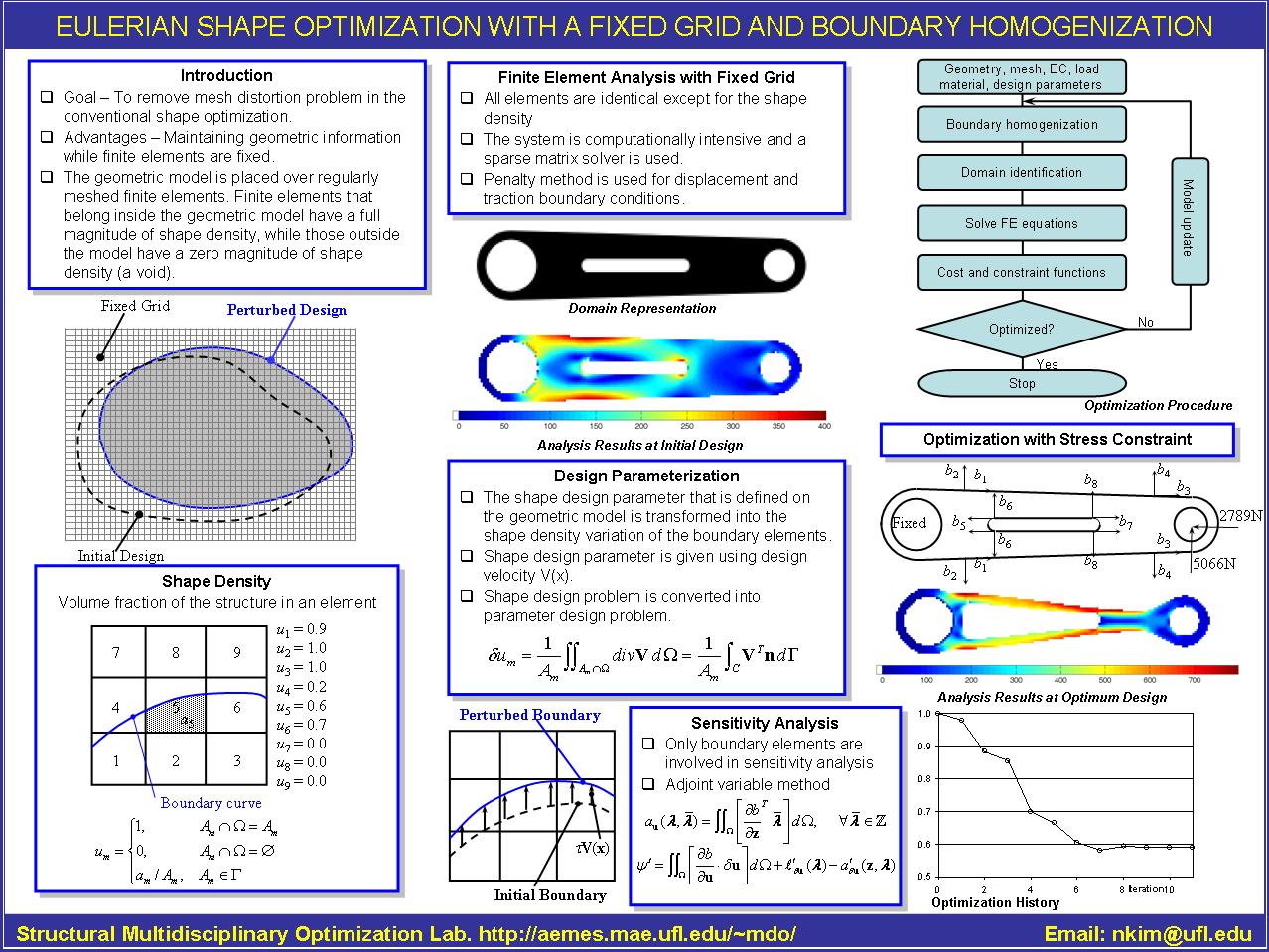
A torque arm shown in Figure 2 is composed of 32 points, 28 boundary curves, and 16 surfaces. A rectangular domain is established with lower-left corner being (-7, -8) and upper-right corner being (49, 8), which covers the whole structure. A 0.471cm Ąŋ 0.471cm square is used to discretize the rectangular domain. Figure 2 also shows the structural domain that is identified using the boundary homogenization method. The black interior domain has a full shape density (u = 1), while the gray boundary represents intermediate shape density (0 < u < 1). For material properties, the following values are use: YoungĄŊs modulus = 207.4 GPa, PoissonĄŊs ratio = 0.3, and thickness = 0.3 cm.
In finite element analysis, the left circle is fixed and horizontal and vertical forces are applied at the center of the right circle. In order to apply for the displacement boundary conditions, the boundary curves that correspond to the left circle are identified first. It is trivial to retrieve boundary element information corresponding to the displacement boundary curves. Then, all nodes that belong to the boundary elements are fixed. Thus, in this approach displacement boundary conditions are applied in a layer of elements. The force boundary condition can also be applied in the same manner.
Maximum stress of about 361 MPa appears at the top and bottom surface of the torque arm (see Figure 3). This result is expected because the applied force is superposition of compressive and bending loads. In addition, relatively high stress concentration is observed at the end of interior slot, which is caused by distortion at the small radius region.
In the mathematical point of view, the pixel-based geometric representation may cause singularity at the non-smooth boundary, which is inevitable when inclined boundary is approximated by x- and y-directional squares. However, the proposed approach reduces such singularity by gradually reducing the shape density at the boundary. However, different material properties between interior and boundary elements cause stress discontinuity. Smoothening algorithm in stress may help to reduce discontinuity.
A simple design optimization problem is posed to minimize the weight of the structure, while satisfying the maximum stress constraint. In order to induce large shape change, a loose constraint limit is deliberately provided. The design optimization problem is converged after eleven number of design iteration. The optimum design reduces more than 40% of the structural weight. The maximum stress at the optimum design appears to be 789 MPa. Figure 4 shows the stress contour plot at the optimum design. The optimization algorithm chose the geometry such that the maximum stress is evenly distributed along the upper and lower regions of the structure. The optimum design conforms to engineering sense because such a beam-like structure the moment of inertia needs to be increased as the moment arm increases.