
MAE operates the High Enthalpy Flow Facility (HEFF) that reproduces flight enthalpies above M = 6.5. This device includes two-stage heating:
- 1. 2 MW electrical heating up to stagnation temperature of T0 = 1200 K, and,
- hydrogen-based vitiated heating in excess of T0 = 1900 K.
Thus, temperatures for flight at M = 4.8 can be attained with no vitiation; flight enthalpies above M = 6.5 can be achieved using the second stage. Thus, minimal vitiation is introduced when operating above Mach 4.8. The air supply enables continuous operation limited only by thermal loads on the hardware for a broad range of operational conditions. The current test section of 1” x 4” cross-section; as comparison, it represents 75% of the cross-section of the facility at AFRL/RQ Laboratories. For most operational conditions of interest, the air supply system ensures continuous operation.
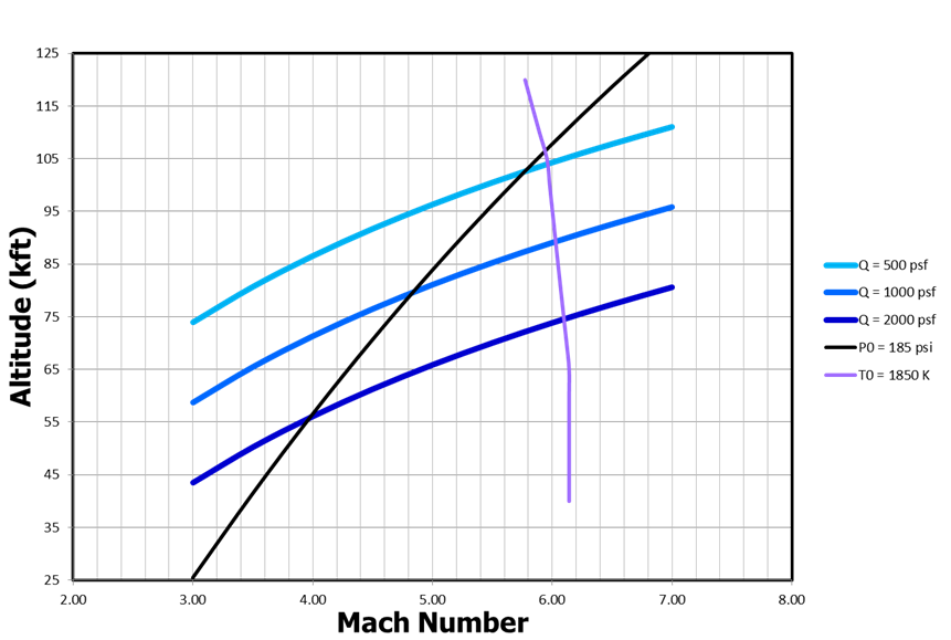
The simulation of flight conditions in terms of altitude/Mach are shown in fig. 1 below. Also shown in the figure are lines of selected flight dynamic pressures.
The electric heater works on a concept that does not include a pressure vessel. As a result, changes in temperature are rapid, of the order of 2-3K/s, therefore capable to reproduce thermal flight transients.
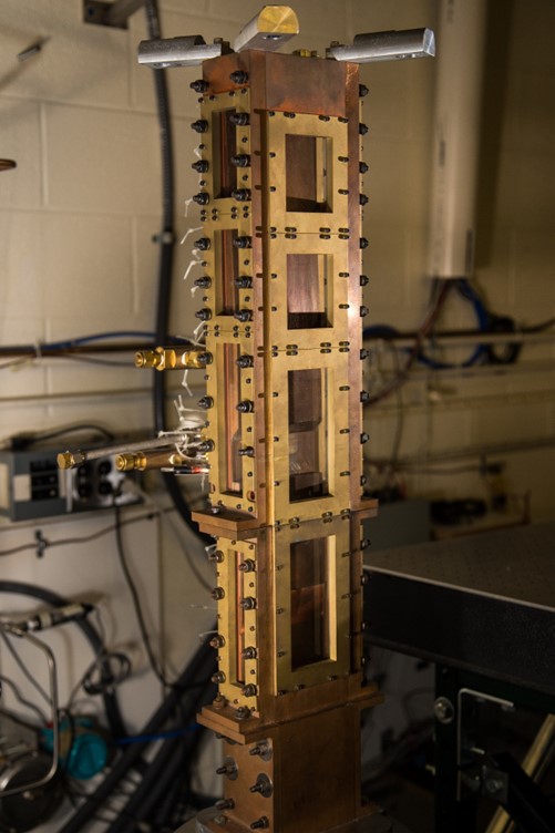
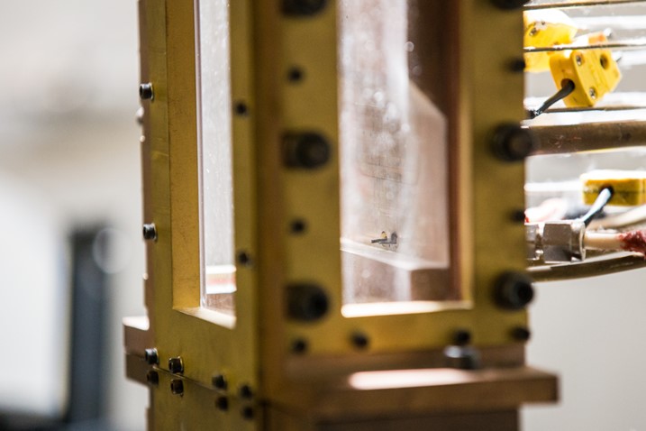
The current test section, shown in Figure 2 with a detail in Figure 3, includes a Mach 2.2 nozzle that connects to a 1” x 4” isolator. The isolator has a constant cross-section and is 8” long. Optical access on three sides is available in both the isolator and the test section. The cavity has a modular construction in the cavity region enabling changes of L/D. Thus L/D of 4, 5 and 6, already build exist to support the proposed research. Two injection locations exist in the cavity, from the front wall and from the cavity floor at 3H inclined at 220 towards the back wall. Aft. injectors add a zone of large fuel flow rates through individual injectors.
The supporting equipment facilitates fuel injection in three independently controlled zones; therefore, modulation of injection in the cavity, upstream and downstream to modify the flowfield pressure can be done indecently. The facility is designed to operate both with gaseous and liquid fuel formulations, therefore an electric heater for liquid fuel heating exists.
Additional support equipment includes a vacuum system that will be used for studies of boundary layer thickness effects on cavity flowfield. A modular element has been designed to remove the boundary layer has been designed to connect upstream or downstream of the isolator to remove all, partially or none of the boundary layer arriving upstream of the isolator. For the project described above this element will need to be manufactured.